


EN-TraceTekTT1100OHP-IM-H58263 01/15
THERMAL BUILDING &
INDUSTRIAL HEAT TRACING SOLUTIONS
4 / 8
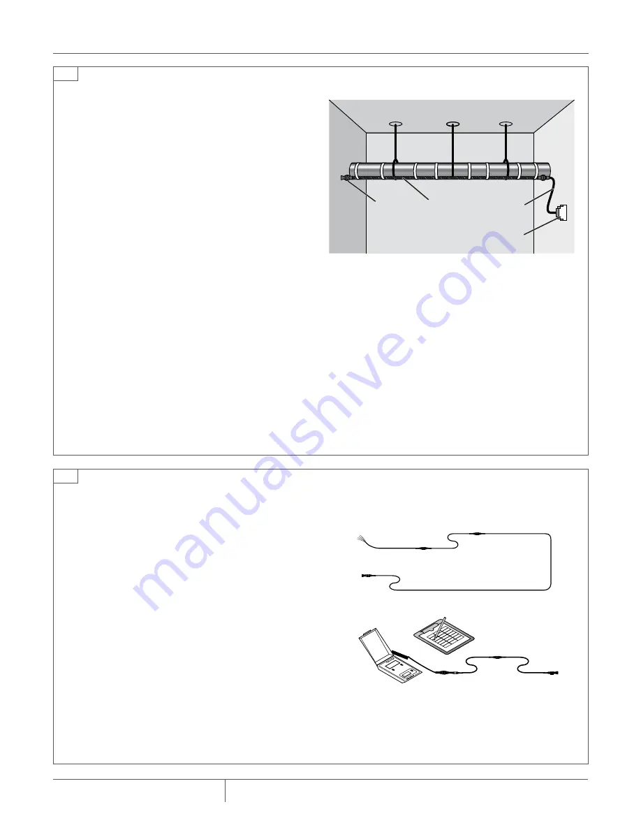
TTC-1, TTSIM-1, TTSIM-1A,
TTSIM-2 or TTDM-128
TT-MET-PC TT1100-OHP TT-MLC-PC
Modular
leader cable
Modular end
termination
5
6
complete the system
1. Install other TraceTek components (such as Modular
Branching Connectors, Weighted Lengths, and Modular
Jumper Cables) as called for in the system layout. Complete
the sensing circuit.
note
: All components of the system have male or female metal
connectors or both. The male connectors are oriented toward
the instrument panel. As new sections of cable are added to
the main leg or branch, each newly added section should end
with an open female connector. The end of each branch or
main leg is terminated with a male end termination.
2. Test the sensing circuit (or portions of it) to confirm that the
sensing cable is clean and intact. Follow the Sensing Cable
Test Procedure.
3. Connect the sensing circuit to the TraceTek alarm module
and activate the system as soon as is practical. Use the
alarm module to monitor the sensing cable during the final
stages of construction.
take precautions if installation is incomplete at end of
work day.
At the end of the work day:
• Ensure that there are no open connectors. Each sensing
cable should be connected to a Modular Leader Cable (TT-
MLC-PC), Modular End Termination (TT-MET-PC), and/or
other sensing cables; check both ends of the cable.
• Test and record the condition of installed sensing cable fol-
lowing the Sensing Cable Test Procedure.
• If practical, connect the installed sensing cable to the
TraceTek alarm module. Test the system and put it in opera-
tion following the alarm module installation instructions.
At the beginning of the next work day:
• Check that the installed sensing cable is clean and intact
following the Sensing Cable Test Procedure. Compare the
results with those obtained at the end of the previous work
day. If necessary, investigate and correct problems before
proceeding.


