29
3. ASSEMBLY PROCEDURE OF MAIN BODY
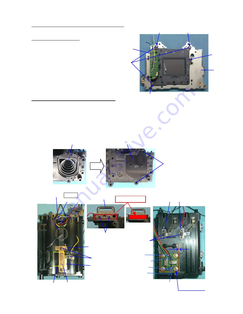
1. 0-E000 (Shutter block)
①
Main body
②
0-E000
③
A70 x3 (Shoulder screws)
*Tighten A70 in numeric order.
④
Arrange 5 lead wires by DT (5x5) as shown in figure.
*After install, 0-E000 has a little movement.
2. A13 (Battery Chamber) and related parts
①
A13 (Battery Chamber) and related parts.
[Confirmation]
Each parts are installed properly.
[Caution]
*
A16: Apply superX (Black) as shown in figure. Do not apply out of red square area.
** Install A75 to 0-T950 properly. Make sure there is no deformation.
There is the gap between side of PC board and A13.
③
②
①
④
③
①
②
TY-CNL-D1.7x3.5
A19
A12
A14
Black, Red
TY-CNL-D
1.7x2.8
A18 (Black, A17)
A23 (Yellow)
A28
DT(2x15)
N300: Super-X x3
White, Red
**A75, W113,
A76(screws) (x4)
**0-T950
Red
Orange
Green
Black
*
A16
TY-CNS2.0x4.5
Super-X (Black)
TY-CNL-D1.7x2.8


