SMART I/O User’s Manual
©1996 PEP Modular Computers GmbH
March 12, 1996
Page 4 - 23
4
Chapter 4 Digital Modules
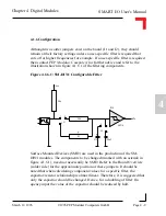
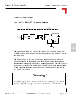
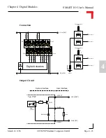
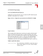
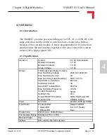
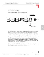
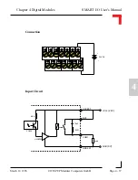
Connection
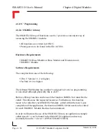
Output Circuit
+Vcc (24V)
Gnd (0V)
OUT0
G03EXT
V01EXT
Typ: PNP
Load
BYM05-100
6.8 k
TIP125
Opto
TLP521
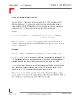
System Interface
User Interface
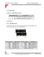
+Vcc (24V)
Gnd (0V)
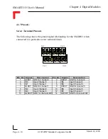
G03EXT
G47EXT
OUT7
OUT3
OUT6
OUT2
OUT5
OUT1
OUT4
OUT0
V01EXT
V45EXT
V23EXT
V67EXT
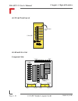
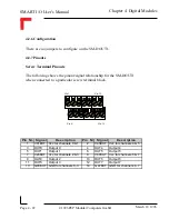
Pin 1
Pin 2
Pin 13
Pin 14
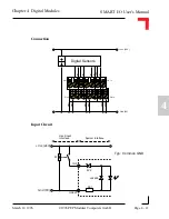
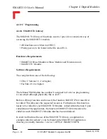
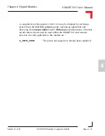
Digital Actuators
Vcc Common (24V)
V01EXT
Channel 0
Channel 1
Vcc Common (24V)
V23EXT
Channel 2
Channel 3
G03EXT
OUT 0
OUT 1
OUT 2
OUT 3


