SMART I/O User’s Manual
©1996 PEP Modular Computers GmbH
March 12, 1996
Page 4 - 29
4
Chapter 4 Digital Modules
4.2.9 ISaGRAF Programming
4.2.9.1 The ISaGRAF Board Parameters
Information on board parameters may be found in the PEP online help and
ISaGRAF online help or user’s manual.
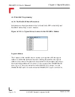
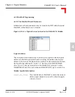
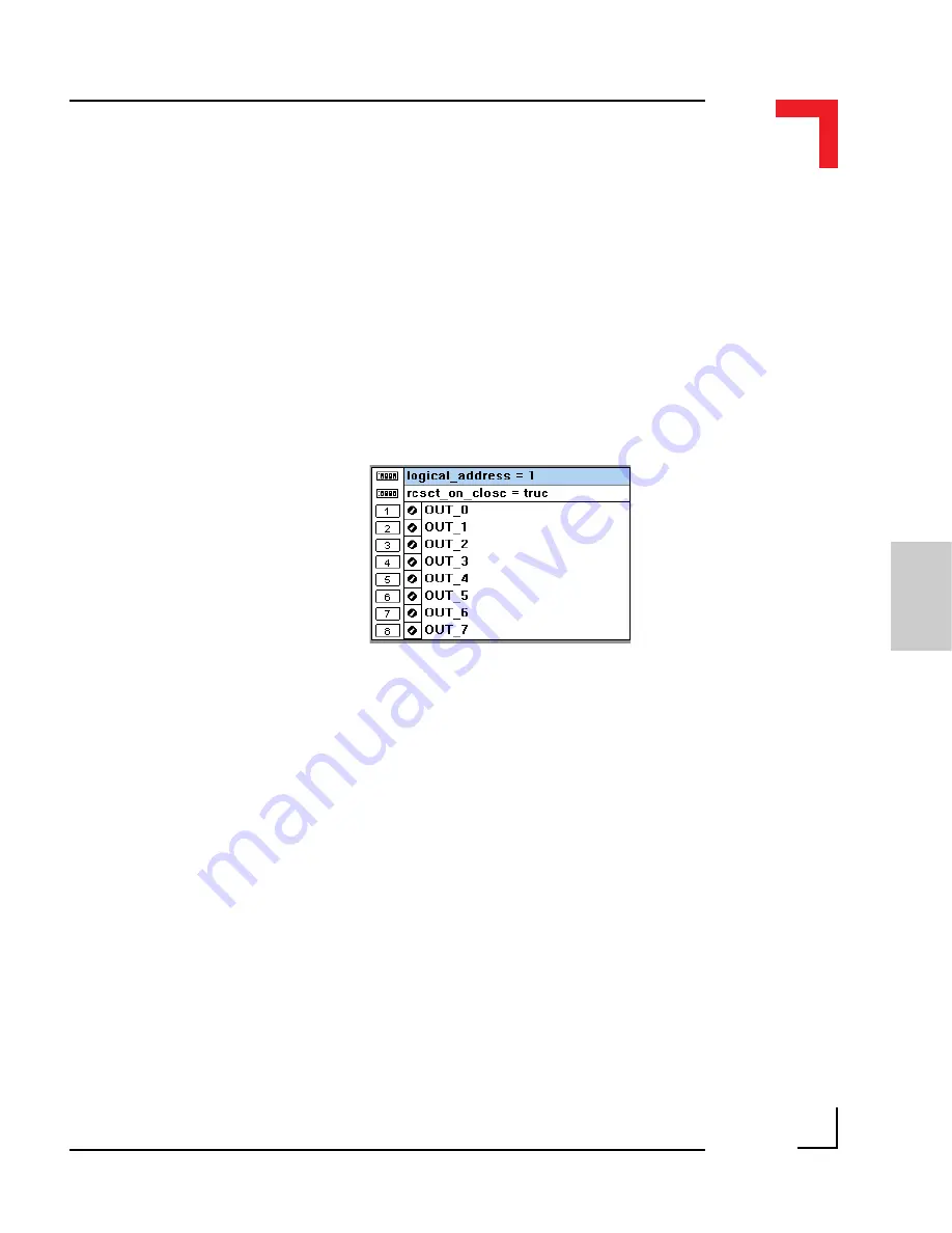
Figure 4.2.9.1.1 a Typical Screen Section for the SM-DOUT1 Module
Logical Address
The 8 outputs of this module may be clearly seen together with the logical
address at which this particular board is residing. Remember, this logical
address is the same as the physical slot position! In the example shown here,
the board being addressed is in slot 1 i.e. the first of the SMART-BASE
slots. Up to 11 slots are catered for in the SMART I/O concept; 3 on the
SMART-BASE and 2 for each connected SMART-EXT (up to a total of 4).
Module Specific Information
reset_on_close
: This variable allows ISaGRAF to return the status of
all the output channels to zero (0V) when the appli-
cation is closed.

