SMART I/O User’s Manual
©1996 PEP Modular Computers GmbH
March 12, 1996
Page 2 - 19
2
Chapter 2 SMART-BASE
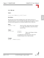
MODE11
The Simple I/O/TIN pin serves as a
timer input and the prescaler is not used. The 24-bit
counter is decremented, rolls over or is loaded from
the counter preload registers following the rising
edge of the TIN pin after being synchronized with
the internal clock.
Output
error_code
SUCCESS
E_BMODE
Unsupported mode
or standard OS-9 error code (refer to the OS-9
Technical Manual Error Codes Section).
Example
RetVal = SMTselIn(MODE00);
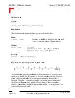
The counter/timer contains a 24-bit synchronous down counter that is loaded
from three 8-bit counter preload registers. The 24-bit counter may be
clocked by the output of a 5-bit (divide by 32) prescaler or by an external
timer input (TIN). If the prescaler is used, it may be clocked by the system
clock (6 MHz CLK pin) or by the TIN external input. The counter signals
the occurrence of an event primarily through zero detection. (A zero is when
the counter of the 24-bit timer is equal to zero). This sets the zero detect
status (ZDS) bit in the timer status register. It may be checked by the proces-
sor or may be used to generate a timer interrupt. The ZDS bit can be reset by
writing a one to the timer status register in that bit position independent of
timer operation.
The general operation of the timer is flexible and easily programmable. The
timer is fully configured and controlled by programming the 8-bit timer
control register. It controls 1) the choice between Simple I/O operation and
the timer operation of the three timer pins, 2) whether the counter is loaded
from the counter preload registers or rolls over when zero detect is reached,
3) the clock input, 4) whether the prescaler is used and 5) whether the timer
is enabled.

