background image

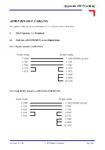
Appendix OS-9 Cabling

Page OS- 4

© PEP Modular Computers

Novemeber 21, 1996

2  

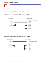
OS-9 System <-> PC

2.1      Software (XON/XOFF) or no Handshake

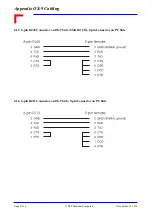
2.1.1  15-pin Connector on OS-9 Side, 25-pin Connector on PC Side

2.1.2  15-pin Connector on OS-9 Side, 9-pin Connector on PC Side

Summary of Contents for VM162

Page 1: ... VM162 VM172 VMEbus Single Board Computer with Manual Order Nr 16596 User s Manual Issue 1 Dual IndustryPack Support ...

Page 2: ......

Page 3: ...Diagram 2 3 2 2 CPU Options 2 4 2 3 Memory 2 4 2 3 1 DRAM FLASH 2 4 2 3 2 SRAM 2 5 2 3 3 Boot ROM optional 2 5 2 3 4 EEPROM 2 6 2 4 Communication Controller 68EN360 QUICC 2 6 2 4 1 Use of 68EN360 Communication Ports 2 6 2 4 2 Use of 68EN360 Memory Controller 2 7 2 4 3 Use of 68EN360 Interrupt Controller 2 7 2 4 4 Use of 68EN360 DMA Channels 2 8 2 5 VMEbus Interface 2 8 2 5 1 VME Master Interface 2...

Page 4: ...2 10 1 Overview 2 30 2 10 2 Features 2 30 2 10 3 Optional IP features not supported 2 30 2 10 4 IP Interface Controller 2 31 2 10 5 IP Reset Control 2 31 2 10 6 IP Clock Control 2 31 2 10 7 IP Interrupt Control 2 31 2 10 8 IP Memory Size Control 2 32 2 10 9 IP Interface Address Map 2 32 2 10 10 IP Interrupt Control Register 2 33 2 10 11 IP Slot Control Register 2 34 2 10 12 IP Connectors 2 35 Chap...

Page 5: ... Protection 3 9 3 3 7 JTAG Chain 3 9 3 3 8 SRAM Data Retention 3 10 3 3 9 BERR1 Timeout 3 10 3 3 10 Backup Current Test Bridge 3 10 Chapter 4 Programming 4 1 4 1 VM162 VM172 Address Map 4 3 4 2 Initializing the 68EN360 4 4 4 3 Initializing the Cache 4 7 Appendices Memory Piggybacks SI6 Piggybacks Bootstrap Loader Controller eXtension Connector OS 9 Cabling Board Layout ...

Page 6: ...VM162 VM172 Table of Contents Page TOC 4 PEP Modular Computers Juli 23 1997 ...

Page 7: ...VM162 VM172 Juli 23 1997 Page 0 1 PEP Modular Computers Preface ...

Page 8: ... batteries for RTC or memory back up ensure that the board is not placed on conductive surfaces including anti static plastics or sponges These can cause shorts and damage to the batteries or tracks on the board When installing piggybacks switch off the power mains Furthermore do not exceed the specified operational temperature ranges of the board version ordered If batteries are present their tem...

Page 9: ...rmation in this document is to the best of our knowledge entirely correct However PEP Modular Computers cannot accept liability for any inaccuracies or the consequences thereof nor for any liability arising from the use or application of any circuit product or example shown in this document PEP Modular Computers reserve the right to change modify or improve this document or the product described h...

Page 10: ...original cost of purchase if appropriate In the event of repair refund or replacement of any part the ownership of the removed or replaced parts reverts to PEP Modular Computers and the remaining part of the original guarantee or any new guarantee to cover the repaired or replaced items will be transferred to cover the new or repaired items Any extensions to the original guarantee are considered g...

Page 11: ...tion 1 1 Product Overview 1 3 1 2 IndustryPack Flexibility 1 3 1 3 Controller eXtension Connector 1 4 1 4 Front Panel and I O Configuration 1 4 1 5 Features 1 6 1 6 Specifications 1 8 1 7 Ordering Information 1 10 1 8 Related Publications 1 11 1 9 Schematic Board Layout 1 12 ...

Page 12: ...VM162 VM172 Chapter 1 Introduction Page 1 2 PEP Modular Computers Juli 23 1997 ...

Page 13: ... and the PEPbug programmed into the FLASH memory residing on one of the DM6xx memory piggybacks The PEP VM162 172 Board Support Package is available for several popular real time operating sy stems OS 9 VxWorks VRTX OS and pSOS 1 2 IndustryPack Flexibility Fully integrated within the VM162 172 CPU boards are two IndustryPack carrier interfaces Each inter face accesses an 8 16 bit databus and suppo...

Page 14: ...a selection of over 30 base CXMs providing analog digital and other I O extensions such as SCSI and fieldbus connection PROFIBUS CAN LON and Bitbus Hence a fea ture of the VM162 172 is that the raw serial signals from the QUICC SCC2 SCC3 and SCC4 chan nels being internally wired to the front panel as well as to the CXC interface Network interfacing is provided if required by ordering the relevant ...

Page 15: ...eT Twisted Pair SI6 PB485 ISO Optoisolated RS485 SCC2 to SCC4 channels support SC 232I Optoisolated RS232 Modem module SC 485I Optoisolated RS485 piggyback Figure 1 1 Front Panel Options U W H RST AB TERM SER1 SER2 SER3 RS485 ISO Tx U W H RST AB ETHERNET 10Base5 ETHERNET Col Tx 10Base2 Col Tx 10BaseT ETHERNET VM162 TERM SER 1 SER 3 SER 2 RST AB IndustryPack Interface B IndustryPack Interface A U W...

Page 16: ...r RS232 operation and can be changed to optoisolated RS232 485 as required by fitting the SC piggyback An SMC1 interface provi des a simple RS232 connection for console debug operations Figure 1 2 MC68EN360 Channel Assignment CXC Interface The 96 pin interface allows other I O possibilities to be realised by utilising PEP s plug in cards such as the CXM PFB12 CXM CAN CXM LON CXM SCSI or CXM SIO3 E...

Page 17: ...he QUICC chip for use by applications requiring DMA trans fer between VMEbus CXC modules DRAM FLASH memory and dual ported SRAM DRAM FLASH This memory complete with a 32 bit wide access bus is placed on a piggyback with addressing capabi lity for up to two memory banks of 64 MByte each The on board programmable FLASH memory al lows the user to produce low cost upgrades by over writing existing sto...

Page 18: ...e MC68EN360 Time Out On board BERR time out min 8µs max 128µs 128µs VMEbus BERR both with software enable disable Watchdog Enabled by software with front panel LED Interrupts VME IRQ1 IRQ7 interrupts enable disable Mask Register SYSFAIL and ACFAIL handlers System Vectors Abort switch level 7 autovector ACFAIL level 7 autovector TICK level 6 vector prog SYSFAIL level 5 autovector Mailbox IRQ level ...

Page 19: ...02 3 and are available on SI6 xx piggybacks SC Interface Serial Interface from MC68EN360 ports SCC2 SCC3 and SCC4 with standard RS232 configuration Power Consumptiona VM162 w MC68060 6 5W 50 MHz VM172 w MC68040 8 5W 33 MHz Temperature 0ºC to 70ºC standard 40ºC to 85ºC extended storage Humidity 0 to 95 non condensing Weight Dimensions 440 g with 10BaseT and memory piggybacks 233mm x 160mm 6U format...

Page 20: ... BASE Same as order no 16026 but with 1 MByte dual ported SRAM 16193 DM 600 Memory Piggyback with 4 MByte DRAM and 1 MByte FLASH memory for VM162 172 11852 DM 600 Memory Piggyback with 4 MByte DRAM and 4 MByte FLASH memory for VM162 172 11853 DM 601 Memory Piggyback with 16 MByte DRAM and 1 MByte FLASH memory for VM162 172 11854 DM 601 Memory Piggyback with 16 MByte DRAM and 4 MByte FLASH memory f...

Page 21: ...k CXC Specification from PEP Version 1 5 or later SI6 10BT IP 10BaseT Twisted pair Ethernet interface piggyback with RJ45 connector 16147 SI6 DUMMY IP Front panel without networking interface s 16028 SI6 PB485 IP Optoisolated RS485 interface piggyback with 9 Pin D Sub connector 16192 SC 2321 Optoisolated RS232 interface piggyback with TxD RxD DTR and CTS signals and Baud rate up to 38 4 kBaud 1291...

Page 22: ...VM162 VM172 Chapter 1 Introduction Page 1 12 PEP Modular Computers Juli 23 1997 1 9 Schematic Board Layout ...

Page 23: ...ster Interface 2 9 2 5 2 System Controller Functions 2 10 2 5 3 VME Slave Interface 2 11 2 5 4 VME Address Map from the VME Side 2 12 2 5 5 VME Control Status Register 2 13 2 6 Board Control Logic 2 14 2 6 1 Boot Decoder Logic 2 14 2 6 2 Interrupt Control 2 14 2 6 3 Bus Timer 2 16 2 6 4 Watchdog Timer 2 16 2 6 5 Board Control Status Register 2 16 2 7 Special Functions 2 18 2 7 1 Real Time Clock 2 ...

Page 24: ... Overview 2 30 2 10 2 Features 2 30 2 10 3 Optional IP features not supported 2 30 2 10 4 IP Interface Controller 2 31 2 10 5 IP Reset Control 2 31 2 10 6 IP Clock Control 2 31 2 10 7 IP Interrupt Control 2 31 2 10 8 IP Memory Size Control 2 32 2 10 9 IP Interface Address Map 2 32 2 10 10 Interrupt Control Register 2 33 2 10 11 Slot Control Register 2 34 2 10 12 Connectors 2 35 ...

Page 25: ...C PB RS232 TTL RS485 10Base2 10Base5 10BaseT RS485 Iso SC PB TTL Backup MDSUB 9 RealTimeClock SI PB Bussizer Buffers Register Bus IRQ Watchdog Board Handler Timer Timer Enhanced CXC Interface Industry Pack Interface FrontPanel Ethernet Fieldbus BoardControlLogic DualPortSRAM VME Interface Buttons Memory PB Master A32 D32 Slave A24 D16 BootROM opt Port SCSI Analog FlatCable Conn IP I O IP I O Seria...

Page 26: ...e performance ratio between them The above measurements have been made under the OS 9 operating system version 3 0 with the Ultra C compiler version 1 3 1 2 3 Memory 2 3 1 DRAM FLASH DRAM and FLASH memory is combined on a piggyback with addressing capabiltity for up to 64 MBy tes each It provides a fast 32 bit data access with DRAM Burst support It provides also in system FLASH programming facilit...

Page 27: ... available with size of 256 kB or 1 MB 2 3 3 Boot ROM optional The VM162 VM172 Boot ROM is an optional socket device The sockets support devices up to 512 kB size with a 16 bit wide data access for PLCC EPROMs By default the board s firmware is stored directly in the FLASH on memory piggyback Thus the Boot ROM is not mandatory In case of using a Memory PB without FLASH or if an application require...

Page 28: ...nion mode In this mode its own CPU32 core is disabled whereas all other features including its Communication Processor Module CPM are still available In terms of communication tasks the QUICC works as a co processor to the CPU Its internal commu nication hardware is built up with a command programmable Communication Processor 14 dedicated DMA channels 4 Serial Communication Controllers SCC 2 Seria...

Page 29: ...gramming Chapter must be closely adhered to 2 4 3 Use of 68EN360 Interrupt Controller The 68EN360 internal interrupt controller is one part of the VM162 VM172 interrupt control logic The 68360 internal interrupt controller provides programmable interrupt vectors for all internal interrupt re quests For detailled description of these interrupts please refer to the 68EN360 User s Manual Additionally...

Page 30: ...to be compatible with CPU VME and DMA VME transfers the board initialization des cribed in the Programming Chapter must be closely adhered to 2 5 VMEbus Interface The VM162 VM172 has a complete VMEbus Master interface with arbiter system clock driver power monitor with system reset driver IACK daisy chain driver and a 7 level VMEbus interrupt handler The VM162 VM172 VMEbus Master interface support...

Page 31: ... VM172 Table 2 5 External Signal Connection Note For the user defined codes 1F 18 and 17 10 there are A24 D16 cycles generated by the VM162 VM172 AM Code Hex Function 3E A24 supervisory program access 3D A24 supervisory data access 3A A24 non privaleged program access 39 A24 non privaleged sata access 2D A16 supervisory access 29 A16 non privaleged access 1F 18 User Defined 17 10 User Defined 0E A...

Page 32: ...Ebus Control Status register 2 5 2 2 SYSCLK Generator TheVMEbus SYSCLK driver of theVM162 VM172 is controlled directly by the FSD bit That means if the board has detected itself as system controller it will automatically drive SYSCLK to the VME bus If it has detected not to be system controller its SYSCLK driver is automatically disabled Note The system integrator has to ensure that there is only ...

Page 33: ... Write cycles TAS instruction used for semaphores are supported in any direction The location of the dual ported SRAM as seen from VME is programmable via the VME Control Status Register There are 16 different base addresses possible with separate enable disable functions all loca ted in VME A23 D16 space Note The lowest 8 kByte of the dual ported SRAM is reserved for generating mailbox interrupts...

Page 34: ... Dual ported SRAM Address Range HEX 0 00 00 00 00 00 00 00 1F FF 00 20 00 0F FF FF 1 10 00 00 10 00 00 10 1F FF 10 20 00 1F FF FF 2 20 00 00 20 00 00 20 1F FF 20 20 00 2F FF FF 3 30 00 00 30 00 00 30 1F FF 30 20 00 3F FF FF 4 40 00 00 40 00 00 40 1F FF 40 20 00 4F FF FF 5 50 00 00 50 00 00 50 1F FF 50 20 00 5F FF FF 6 60 00 00 60 00 00 60 1F FF 60 20 00 6F FF FF 7 70 00 00 70 00 00 70 1F FF 70 20 ...

Page 35: ...are initializes EN_DTR EN_BERR2 and BADR 3 0 during startup follo wing default parameters stored in the serial EEPROM Name Value Reset HW Slot 1 Other Reset PEP SW Slot 1 Other Description P_IRQ5 bit 7 EN_DPR bit 6 EN_BERR2 bit 5 FSD bit 4 BADR3 BADR0 bits 3 0 1 1 1 1 0 0 0 0 0 0 1 0 0 0 0 0 Value stored in EEPROM 1 0 1 0 Value stored in EEPROM Pending mailbox IRQ Dual port RAM inc mailbox IRQ for...

Page 36: ...boot device the optional Boot ROM can be used as a standard ROM for storing program data or application specific parameters 2 6 2 Interrupt Control The interrupt control logic processes internal interrupt requests 68EN360 together with external re quests VME and external autovectored interrupt requests The interrupt control logic is built up using the 68EN360 internal interrupt controller for QUIC...

Page 37: ... Interrupt Mask Register is a one byte wide register with read write access situated at default address CD 00 00 01 HEX All bits are cleared after reset Note The firmware of the board initializes this register using the default parameters stored in the EE PROM Register Description Source 68EN360 Pin Autovector ABORT ACFAIL IRQ7 7 TICK IRQ6 6 Mailbox IRQ IRQ5 5 SYSFAIL IRQ3 3 Name Value Description...

Page 38: ... is monitored by the on board Bus Timer VMEbus cycles themselves are monitored by the separate VME Bus Monitor 2 6 4 Watchdog Timer A 512ms watchdog timer is also provided by the VM162 VM172 Once enabled via the Board Control Status Register the watchdog timer cannot be reset by software It must be re triggered via the corre sponding bit in the Board Control Status Register periodically within the...

Page 39: ...fied within the 68EN360 Set by VMEbus BUS monitor when timeout has been reached Used to identify BERR caused by this timer see also VMEbus Control Status Register Set by on board bus error timer when timeout has been reached Used to identify BERR caused by this timer Enable the watchdog timer It can only be set once and remains enabled until the next reset Triggers the watchdog timer Watchdog time...

Page 40: ...information on the EEPROM please refer to the XICOR X25C02 data sheet 2 7 3 TICK Timer The 68EN360 internal Periodic Interrupt Timer is used by the PEP supported real time operating sy stems as TICK generator For more information please refer to the 68EN360 User s Manual 2 7 4 General Purpose Timer There are four 16 bit general purpose timers available which are provided by the 68EN360 Two pair of...

Page 41: ...es from the VME 5V Stby to the on board Gold Caps au tomatically The on board Gold Caps are continuously reloaded via the 5V Stby line The 5V Stby current is typically 7mA for a few minutes when the Gold Caps are at the beginning of the loading phase fully dischaged 2 7 7 Front Panel Buttons and LED Ports Figure 2 1 LED Port and Button Location 2 7 7 1 RESET ABORT Button A RESET button is fitted t...

Page 42: ...re 2 2 MC68EN360 Channel Assignment This translation between the raw 68EN360 signals and ready configured port on the front panel is very flexible on the VM162 VM172 by using SI and SC piggybacks or even CXMs 5 configured serial ports are available on the front panel connectors The Table on the following page shows the availability of the various logical serial ports on the internal interfaces for...

Page 43: ...iggybacks are available at the moment for the 3 standard Ethernet versions 10Base5 AUI 10Base2 and 10BaseT Additionally an isolated RS485 interface is available with 9 pin D Sub frontpanel con nector which is especially designed for Fieldbus applications available as well as a standard RS232 in terface for more information please refer to the SI Piggyback Appendix in this manual 68EN360 Resource D...

Page 44: ...ybacks in the SC product line These ports are usually used for communication between systems or to subsy stems modems In addition the signals of SCC2 SCC3 and SCC4 are routed to the CXC This is mainly useful for phy sical adaptions where the application requirements cannot be met using SC piggybacks SER1 SER2 and SER3 Pinouts RJ45 Connector Mini D Sub Female Connector N C Not Connected Pin Signal ...

Page 45: ...ixed to RS232 interfaces This port supply RxD TxD interfaces with soft ware handshake XON XOFF capability Usually this port is used as terminal debug port RJ45 Connector Mini D Sub Female Connector N C Not Connected Pin Signal 1 N C 2 N C 3 GND 4 TxD 5 RxD 6 N C 7 N C 8 DTR Pin Signal 1 N C 2 RxD 3 TxD 4 N C 5 GND 6 N C 7 N C 8 N C 9 N C ...

Page 46: ... A Signals Row B Signals Row C Signals 1 2 3 4 5 6 7 8 9 10 11 12 13 14 15 16 17 18 19 20 21 22 23 24 25 26 27 28 29 30 31 32 PC0 _RTS1 L1ST1 PC1 _RTS2 L1ST2 PC2 _RTS3 _L1RQB L1ST3 PC3 _RTS4 _L1RQA L1ST4 PB0 _SPISEL _RRJCT1 PB1 SPICLK _RSTRT2 VCC PB2 SPIMOSI SPITXD _RRJCT2 PB3 SPIMISO SPIRXD BRGO4 PB8 _SMSYN1 _DREQ2 PB16 BRGO3 STRBO PB9 _SMSYN2 _DACK2 PB17 _RSTRT1 STRBI VCC _CS CXC CS5 of 68360 _A...

Page 47: ... a2 Yes PC1 IRQ_3 a3 Yes PC2 IRQ_4 a4 Yes PC3 CXC Function Pin Nr 68302 HW Compatible 68 EN 360 Port Comment DMA_ACK c2 Yes PB5 DMA_REQ c3 Yes PB4 CXC Function Pin Nr 68302 HW Compatible 68 EN 360 Port Comment SER1_RCLK b1 Yes PA8 SER1_TCLK b2 Yes PA10 SER1_TXD b4 Yes PA3 SER1_RXD b10 Yes PA2 SER1_RTS b5 Yes PB13 SER1_DTR a13 Yes PB17 SER1_CTS b13 Yes PC6 SER1_CD b14 Yes PC7 ...

Page 48: ...11 Yes PC9 CXC Function Pin Nr 68302 HW Compatible 68 EN 360 Port Comment SER3_RCLK c6 Yes PA15 Not usable if SI Module uses SCC4 See note 4 SER3_TCLK c5 Yes PA14 SER3_TXD c8 Yes PA7 Not usable if SI Module uses SCC4 See note 4 SER3_RXD c9 Yes PA6 Not usable if SI Module uses SCC4 See note 4 SER3_RTS b7 Yes PB15 Not usable if SI Module uses SCC4 See note 4 SER3_DTR a12 Yes PB9 Not usable if SI Mod...

Page 49: ...not both at the same time Due to this a conflict exists if the SCC4 port is to be used with the SI232 piggyback and CXC boards such as CXM SIO3 as both boards access this port The SCC4 port can therefore not be used at the same time by SI piggybacks and CXC boards CXC Function Pin Nr 68302 HW Compatible 68 EN 360 Port Comment user defined a5 No PB0 Used on board SPI SEL for EEPROM Cannot be used o...

Page 50: ...2 time division multiplexed channels via the CXC ISDN PCM GCI and so on Multi function pins with incompatible functions with regard to the 68302 and 68EN360 called user defined in the generic CXC specification are not part of the VM162 VM172 CXC specification Although the SMCs are configured on the base board these ports are also integrated on the CXC This is because of possible ISDN applications ...

Page 51: ...e frame address did not match I Clocks CLK8 CLK1 Input clocks to the SCCs SMAs SI and the baud rate generators I IDMA DMA Request _DREQ2 _DREQ1 A request input to an IDMA channel to start an IDMA transfer I DMA Acknowledge _DACK2 _DACK1 An acknowledgement output by the IDMA that an IDMA transfer is in progress O DMA Done _DONE2 _DONE1 A bidirectional signal that indicates the last IDMA transfer in...

Page 52: ...nd memory space are fixed within the address map 2 10 2 Features up to standard IPs or 1 double sized IP supports I O ID Memory and Interrupt Acknowledge cycles supports 8 bit and 16 bit IP cycles IP slot control register set of two per IP slot programmable IP bus speed 8 or 32 MHz individual IP bus speed per slot 2 interrupts per IP programmable level from 1 to 7 up to 8 MB linear memory space pe...

Page 53: ...fter detecting that the assembled IP module supports also 32 MHz by reading information stored within the module s ID PROM the IP clock can be switched to 32 MHz by setting bit 5 of the IP slot control register On the IP interface controller there are implemented in parallel separate clock generators and state ma chines for the different IP bus speeds Therefore each IP slot can operate at its indi...

Page 54: ...ce 2 10 9 IP Interface Address Map IPa IPb Note Whether 1 or 8 MByte memory address space is selected depends on the memory size bit within the IP slot control register Depending on the memory size bit the memory page bits are relevant or not Default is 8 MByte not paged Base Address HEX Size Port Width Device CE 00 08 00 128 Byte D8 D16 IP Slot a IO Space CE 00 08 80 128 Byte D8 D16 IP Slot a ID ...

Page 55: ...ite Value after Reset HEX 00 Bit 7 Bit 6 Bit 5 Bit 4 Bit 3 Bit 2 Bit 1 Bit 0 INT1_EN INT1_IL2 INT1_IL1 INT1_IL0 INT0_EN INT0_IL2 INT0_IL1 INT0_IL0 INT1_EN 0 IP interrupt request on INT1 line disabled 1 IP interrupt request on INT1 line enabled INT1_IL2 0 IP IRQ level for INT1 line 1 or 3 or 5 or 7 INT0_EN 0 IP interrupt request on INT0 line disabled 1 IP interrupt request on INT0 line enabled INT0...

Page 56: ...rmat byte Access read and write Value after Reset HEX 00 Bit 7 Bit 6 Bit 5 Bit 4 Bit 3 Bit 2 Bit 1 Bit 0 reserved reserved IP_CLK IP_RESET M_SIZE M_PAG2 M_PAG1 M_PAG0 IP_CLK 0 IP CLOCK 8 MHZ 1 IP CLOCK 32 MHZ IP_RESET 0 0 IP RESET line active 1 IP RESET line not active IP enabled M_SIZE 0 IP linear addressable mem space 8 MB 1 IP linear addressable mem space 1 MB M_PAG active memory page 1 of 8 1 ...

Page 57: ...ignals whereas the other one near to the frontpanel carries the IP I O signals The IP I O signals are routed from the 50 pin IP I O connector to a 50 pin flatcable connector and also to the 50 pin frontpanel DSUB connector There is a one to one correspondance between the pin si gnal numbers between the IP I O connector flatcable connector and DSUB connector VME Connector VME Connector VME P2 IPb V...

Page 58: ...5 Pin 26 27 28 29 30 31 32 33 34 35 36 37 38 39 40 41 42 43 44 45 46 47 48 49 50 IP I O 26 27 28 29 30 31 32 33 34 35 36 37 38 39 40 41 42 43 44 45 46 47 48 49 50 Pin 1 2 3 4 5 6 7 8 9 10 11 12 13 14 15 16 17 18 19 20 21 22 23 24 25 IP I O 1 2 3 4 5 6 7 8 9 10 11 12 13 14 15 16 17 18 19 20 21 22 23 24 25 Pin 26 27 28 29 30 31 32 33 34 35 36 37 38 39 40 41 42 43 44 45 46 47 48 49 50 IP I O 26 27 28...

Page 59: ... Pinout Pin 1 2 3 4 5 6 7 8 9 10 11 12 13 14 15 16 17 18 19 20 21 22 23 24 25 IP I O 1 2 3 4 5 6 7 8 9 10 11 12 13 14 15 16 17 18 19 20 21 22 23 24 25 Pin 26 27 28 29 30 31 32 33 34 35 36 37 38 39 40 41 42 43 44 45 46 47 48 49 50 IP I O 26 27 28 29 30 31 32 33 34 35 36 37 38 39 40 41 42 43 44 45 46 47 48 49 50 Pin1 Pin50 Pin26 Pin25 ...

Page 60: ...VM162 VM172 Chapter 2 Functional Description Page 2 38 PEP Modular Computers Juli 23 1997 This page has been intentionally left blank ...

Page 61: ...ion Component Side 3 4 3 2 1 VME Boot 3 5 3 2 2 ROM Boot 3 5 3 2 3 Protective Ground Signal Ground 3 5 3 2 4 VME SYSRES 3 5 3 2 5 CXC Mode 3 6 3 3 Jumper Description Solder Side 3 7 3 3 1 CPU Type 3 8 3 3 2 CPU Power Supply 3 8 3 3 3 CPU Bus Clock 3 8 3 3 4 SRAM Size 3 8 3 3 5 Communications Clock 3 9 3 3 6 EEPROM Write Protection 3 9 3 3 7 JTAG Chain 3 9 3 3 8 SRAM Data Retention 3 10 3 3 9 BERR1...

Page 62: ...VM162 VM172 Chapter 3 Configuration Page 3 2 PEP Modular Computers Juli 23 1997 ...

Page 63: ... Open Boot from boot ROM disabled J10 Set On board reset generator to VME J11 Open Enhanced CXC mode disabled J8 Open Protective ground disconnected from signal ground solder jumper Jumper Default Setting Description J3 Dependent on board version CPU type J12 J15 Dependent on board version CPU power supply J5 J7 Dependent on board version CPU clock speed J4 Set 24 MHz Comm Clock connected to 68EN3...

Page 64: ...scription Component Side Figure 3 1 VM162 VM172 Jumper Layout Component Side VME Connector VME Connector VME Connector P2 RJ45 Mini D Sub Serial port Connectors RJ45 RJ58 or 15 Pin D Sub Connector VME Connector P1 J8 Protective GND Signal GND J1 VME Boot J2 ROM Boot VME SYSRES J10 J11 CXC Mode ...

Page 65: ...ation the VM162 VM172 uses the VMEbus RESET line This behaviour may not be wanted in multi master configurations and can be disconnected Jumper Setting Description J1 Open Boot from VMEbus enabled Set Boot from VMEbus disabled Default Jumper Setting Description J2 Set Boot from boot ROM enabled Open Boot from boot ROM disabled Default Jumper Setting Description J8 Set Protective ground connected t...

Page 66: ...he multiplexing of the CXC address lines in order to enhance the address range to 16MByte This is used today in conjunction with the CXM PFB12 PROFIBUS board Please consult the relevant CXM User s Manual to set the CXC mode Jumper Setting Description J11 Set Enhanced CXC mode enabled Open Enhanced CXC mode disabled Default ...

Page 67: ...Description Solder Side Figure 3 2 VM162 VM172 Jumper Layout Solder Side V M E C o n n e c t o r VME Connector P1 V M E C o n n e c t o r VME Connector P2 RJ45 Mini D Sub Serial port Connector s RJ45 RJ58 or 15 Pin D Sub Connector J9 J20 J16 J19 J22 J5 J6 J4 J15 J14 J13 J12 J17 J18 J21 J23 J3 ...

Page 68: ...ion J3 Set CPU type is 68060 Open CPU type is 68040 or 68040V Jumper Setting Description J12 J15 1 2 CPU power is 5 volt 68040 1 3 CPU power is 3 3 volt 68040V or 68060 Jumper Setting Description J5 J6 J5 J7 Set Set CPU Bus clock is 25 0 MHz Open Set CPU Bus clock is 33 3 MHz Jumper Setting Description J19 J20 J19 J20 1 2 1 2 SRAM size is 1 MByte 1 3 1 3 SRAM size is 256 kByte ...

Page 69: ...OM Write Protection The serial EEPROM stores important data such as the PEP assigned Ethernet address In order to pre vent overwriting users may set the protection 3 3 7 JTAG Chain Jumper Setting Description J4 Set 24 MHz connected to 68EN360 RCLK2 pin Default Open 24 MHz disconnected from 68EN360 RCLK2 pin Jumper Setting Description J9 Set Serial EEPROM write protected Open Serial EEPROM not writ...

Page 70: ...imeout This jumper sets the timeout of the BERR1 and can be used for debugging purposes 3 3 10 Backup Current Test Bridge This jumper is reserved for support usage Jumper Setting Description J16 1 2 SRAM data retention is off 1 3 SRAM data retention is on Default Jumper Setting Description J17 J18 J21 J17 J18 J21 Set Open Open 8µs BERR1 tineout Open Set Open 32µs BERR1 timeout Open Open Set 128µs ...

Page 71: ...VM162 VM172 Chapter 4 Programming July 19 1997 Page 4 1 PEP Modular Computers Programming 4 1 VM162 VM172 Address Map 4 3 4 2 Initializing the 68EN360 4 4 4 3 Initializing the Cache 4 7 ...

Page 72: ...VM162 VM172 Chapter 4 Programming Page 4 2 PEP Modular Computers July 19 1997 ...

Page 73: ...0 00 85 00 00 00 87 00 00 00 8D 00 00 00 8F 00 00 00 90 00 00 00 A0 00 00 00 B0 00 00 00 16 MB 16 MB 64 KB 16 MB 64 KB 16 MB 256 MB 256 MB 256 MB VME VME VME VME VME VME VME VME VME VMEbus A24 D16 type AM 1F 18 VMEbus A24 D16 type AM 17 10 VMEbus A16 D16 type AM 2D 29 VMEbus A24 D16 type AM 3E 3D 3A 39 VMEbus A16 D32 type AM 2D 29 VMEbus A24 D32 type AM 3E 3D 3A 39 VMEbus A32 D16 type AM 0E 0D 0A ...

Page 74: ...L MBAR in CPU space Example move l 7 d1 select CPU space move l 7000001 d0 value to write to MBAR movec d1 dfc select CPU space moves l d0 MBAR set MBAR 2 Clear reset status register 0xFF B RSR 3 Set system protection register bus monitor enabled 128 system clocks timeout 0x7 B SYPCR 4 Set module configuration register bus request MC68040 arbitration ID 3 arbitration synchronous timing mode bus cl...

Page 75: ...hip Select lines are initialized in the sequence shown below It should also be noted that the following values need to be changed for various configurations of the on board memory see note below CS0 FLASH to 0x4000000 negate timing 040 0x4000011 L BR0 CS0 size to 16 MByte port size 32 bit tcyc 3 0x3F000000 L OR0 CS1 size to 64 MByte port size 32 bit tcyc 0 bcyc 1 0xC000001 L OR1 CS1 DRAM to 0x0 bu...

Page 76: ...ve this is to write a pattern to the first location and then search for that pattern at meaningful distances e g 256kB 512 kB 1 MB 2 MB 4 MB 8 MB 16 MB If the pattern is found at such an address the original pattern must be altered and then checked to see if the mirrored pattern changes in the same way If not the search must be continued or if yes the memory size is found Note The MC68040 normally...

Page 77: ...C00010C4 CICR 0xC0001540 SDCR 0xC000151E VCSR 0xCD000005 BCSR 0xCD000007 4 3 Initializing the Cache Before the system enables any cache present they should be invalidated using cinva bc Furthermore the complete address range should not be cachable as caching only makes sense on DRAM and FLASH EPROM Other areas should never be cached and must be switched to serialized in order to prevent the MC6804...

Page 78: ... Modular Computers July 19 1997 Accesses to the DRAM and FLASH should be made at 0 and 4000000 All other components addres sed by the MC68EN360 should always be accessed over the mirrored area with Cxxxxxxx as descri bed in the Address Map Section ...

Page 79: ...he piggyback options are described in the following sections Ordering Information Name Description Order No DM600 Memory piggyback with 4 MByte DRAM and 1 MByte FLASH 11852 DM600 Memory piggyback with 4 MByte DRAM and 4 MByte FLASH 11853 DM601 Memory piggyback with 16 MByte DRAM and 1 MByte FLASH 11854 DM601 Memory piggyback with 16 MByte DRAM and 4 MByte FLASH 11855 DM602 Memory piggyback with 1 ...

Page 80: ...h Write Protection Setting Descirption 1 MB FLASH 8 x 29F010 4 MB FLASH 8 x 29F040 Open All Flash EPROM write protected 1 2 No Protection Default 1 3 Flash bank 1 write protected Default address range upper 512 kB 4008000 40100000 upper 2 MB 4020000 40400000 1 4 Flash bank 0 write protected Default address range lower 512 kB 4000000 40080000 lower 2 MB 4000000 40200000 FLASH Bank 1 Bank 0 1 4 3 2 ...

Page 81: ...Flash Write Protection Setting Descirption 1 MB FLASH 8 x 29F010 4 MB FLASH 8 x 29F040 Open All Flash EPROM write protected 1 2 No Protection Default 1 3 Flash bank 1 write protected Default address range upper 512 kB 4008000 40100000 upper 2 MB 4020000 40400000 1 4 Flash bank 0 write protected Default address range lower 512 kB 4000000 40080000 lower 2 MB 4000000 40200000 FLASH Bank 1 Bank 0 1 4 ...

Page 82: ...J1 Flash Bank 1Write Protection Jumper J2 Flash Bank 0 Write Protection Setting Descirption 1 MB FLASH 8 x 29F010 Set No Protection Default Open Flash bank 1 write protected Default address range upper 512 kB 4008000 40100000 Setting Descirption 1 MB FLASH 29F010 Set No Protection Default Open Flash bank 0 write protected Default address range lower 512 kB 4000000 40080000 FLASH Bank 1 Bank 0 J1 J...

Page 83: ...Computers 4 DM603 The DM603 is a memory piggyback fitted with 32MByte DRAM and either 0 5MByte or 2MByte Flash EPROM 4 1 Jumper Location Jumper J1 Flash Write Protection Setting Descirption Open All Flash EPROM write protected Set No Protection Default FLASH J1 DRAM ...

Page 84: ...Write Protection Setting Descirption 1 MB FLASH 8 x 29F010 4 MB FLASH 8 x 29F040 J1 J2 open All Flash EPROM write protected J1 J2 set No Protection Default J1 open Flash bank 1 write protected Default address range upper 512 kB 4008000 40100000 upper 2 MB 4020000 40400000 J2 open Flash bank 0 write protected Default address range lower 512 kB 4000000 40080000 lower 2 MB 4000000 40200000 FLASH Bank...

Page 85: ...optoisolated PROFIBUS with SI6 PB485 ISO piggyback Each of the piggyback options is described in the following Sections Ordering Information Name Description Order No SI6 10B2 10Base2 Thin Ethernet cheapernet interface with RG58 coax connector 15058 SI6 10B5 10Base5 AUI Ethernet interface piggyback with 15 pin D Sub connector 15059 SI6 10BT 10BaseT Twisted pair Ethernet interface piggyback with RJ...

Page 86: ...roller chip It connects one of the range of PEP CPU boards to a 50Ω coax cable via an RG58 BNC T connector The SI6 10B2 has two LEDs fitted a red LED indicates collision detection and a yellow LED for data 1 1 Specifications 1 2 Connector On board termination Max Baud Rate None Cheapernet cable is terminated at both ends 10 Mbit s as specified by Ethernet ...

Page 87: ...al On board termination Max Baud Rate None Cheapernet cable is terminated at both ends 10 Mbit s as specified by Ethernet Pin No Signal Pin No Signal 1 Control In circuit Shield 9 Control In circuit Shield 2 Control In circuit A 10 Data out circuit B 3 Data out circuit A 11 Data out circuit Shield 4 Control In circuit Shield 12 Data in circuit B 5 Data in circuit A 13 12 Volts 6 Voltage Common 14 ...

Page 88: ...ielded 100Ω twisted pair cable via an RJ45 telephone jack The SI6 10BT has two LEDs fitted a red LED indicates collision detection and a yellow LED for data 3 1 Specifications 3 2 Connector On board termination Max Baud Rate 100Ω 10 Mbit s as specified by Ethernet Pin No Signal 1 TD 2 TD 3 RD 4 Not connected 5 Not connected 6 RD 7 Not connected 8 Not connected Col Tx 10BaseT ETHERNET Collision Dat...

Page 89: ...1 Squelch Threshold Jumper J2 Link Test Jumper J3 Shielding Setting Descirption Open Normal Default Set 4 5dB reduced threshold Setting Descirption Open Link Test enables Default Set Link Test disabled Setting Descirption Open Unshielded 100Ω termination Default Set Shielded 150Ω termination J2 J1 J3 ...

Page 90: ...ansmission 4 1 Specifications 4 2 Connector On board termination Isolation Voltage Max Baud Rate 150Ω jumper selectable Optocoupler specified up to 2 5 kV 10 Mbit s as specified by Ethernet Pin No Signal Description 1 SHIELD Shield Protective Ground resp 2 RP Reserved for power 3 RxD TxD Receive Transmit Data 4 CNTR Control 5 DGND Data Ground 6 VP Voltage Plus 7 RP Reserver for power 8 RxD TxD Rec...

Page 91: ...J6 Received Control Setting Descirption Open No internal line termination Default Set Internal line termination Setting Descirption Open No internal idle status Default Set Internal idle status Setting Descirption 1 3 Isolating VCC supplied internally Default 1 2 Isolating VCC supplied externally Setting Descirption 1 3 Receive permanently enabled Default 1 2 Receive enabled J3 J3 J2 J1 J5 J6 2 13...

Page 92: ...Appendix SI6 Piggybacks Page SI6 8 PEP Modular Computers Juli 23 1997 This page has been intentionally left blank ...

Page 93: ...from MOTOROLA S records or from an abso lute address If the programmed image does not work the Bootstrap Loader can be entered again The memory contents can be examined and another programming cycle initiated The Bootstrap Loader is delivered already installed in DM60x memory piggybacks Please read this user manual before reprog amming any FLASH memory WARNING When programming FLASH memory NEVER p...

Page 94: ...ntents or change the BootWaitTime The serial term port operates at 9600 Baud 8 bits character 1 stop bit and no parity 2 2 Entering the Command Mode There are two possible cases lf no valid start key was found the Bootstrap Loader s command mode is entered automatically1 If the user wants to enter the Bootstrap Loader manually e g for re programming the FLASH contents he must use the ABORT button ...

Page 95: ...f Sl or S2 record input is preferred please note that these records only include 16 and 24 bit wide addresses Therefore in order to reach the FLASH area an address offset must be specified using the o option of the If command Additio nally it must ensured that the code is not larger than the covered address range Note The If command cannot be used to provram Motorola S records to RAM areas For the...

Page 96: ...s assumed to be a PC with Windows Windows95 or WindowsNT A serial cable is used to connect the ser0 port of the board to program to COM2 of the PC Additionally we assume that we want to program a Motorola S record built for address 0 e g theVxWorks file bootrom hex The serial connection should run at 19200 Baud The following steps must be performed Host In a DOS Window configure the COM 2 port to ...

Page 97: ... in this case the loader programs in the background by default and the propagation of the process cannot be monitored It is recommended that by default the programming over the ser0 port should be used If the process must be aborted press the ABORT button and try again 3 3 Programming from an Absolute Address The second possibility to program FLASH memory is to program it from an absolute address ...

Page 98: ... the serial EEPROM This section is validated with a CRC code to avoid the setting of random parameters If the CRC of the Boot section is not valid the BootWaitTime can be changed but this change has no effect because the bw command does not validate an invalid CRC to avoid undesired side effects In this case the default of 5 seconds is always used To validate an invalid CRC the appropriate utility...

Page 99: ...ffset u q c m adr I len Description Without parameters the FLASH is loaded using S records over the term port offset is a signed 32 bit offset which is added to every record and can be used to move the S records to the FLASH po sition Note This ontion must be used if 51 or S2 records are used u must be used to download over ser0 q suppress all messages except error messages c clears all untouched ...

Page 100: ... baud specifies the baud rate The values 50 75 110 134 5 150 300 600 1200 1800 2000 2400 3600 4800 7200 9600 19200 and 38400 Baud can be specified bitschar specifies the bits character Valid values are 7 or 8 parity specifies if parity should be checked generated The value n specifies none o for odd and e for even parity Stops specifies the stopbits which will be generated Valid values are 1 or 2 ...

Page 101: ...cription This command exits the Bootstrap Loader and resets the system It terminates the Bootstrap Loader command mode and resets the complete system generating a system reset with the on board watchdog 4 6 Help Syntax or help Description This command prints the online help page ...

Page 102: ...Appendix Bootstrap Loader Page BOOT 10 PEP Modular Computers Juli 23 1997 This page has been intentionally left blank ...

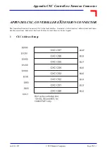
Page 103: ... Computers APPENDIX CXC CONTROLLER EXTENSION CONNECTOR The Controller eXtension Connector CXC is the local interface It contains a 16 bit data bus 7 address lines and 8 deco ded chip select lines Each select line has 256 bytes In total there are 8 select signals 1 CXC Address Range ...

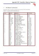
Page 104: ...RCLK 7 Vcc SER3_RTS Vcc 8 user defined SER3_CD SER3_TXD 9 user defined GND SER3_RXD 10 user defined SER1_RXD user defined 11 SER2_DTR user defined SER2_CD 12 SER3_DTR GND SER2_RTS 13 SER1_DTR SER1_CTS SER2_CTS 14 Vcc SER1_CD Vcc 15 _CS CXC GND SER2_TCLK 16 _AS SER3_CTS SER2_RCLK 17 R _W _SYSR SER2_TXD 18 _UDS GND SER2_RXD 19 _LDS _EDTACK Vcc 20 Vcc CXC CLK _CS2 21 A1 GND _CS3 22 A2 _CS0 _CS4 23 A3...

Page 105: ...XD _RRJCT2 PB3 SPIMISO SPIRXD BRGO4 PB8 _SMSYN1 _DREQ2 PB16 BRGO3 STRBO PB9 _SMSYN2 _DACK2 PB17 _RSTRT1 STRBI PA8 CLK1 BRGO1 L1RCLKA TIN1 PA10 CLK3 BRGO2 L1TCLKA TIN2 PA3 TXD2 PB13 _RTS2 L1ST2 PB15 _RTS4 _L1RQA L1ST4 PC11 _CD4 _L1RSYNCA PA2 RXD2 PB10 SMTXD2 L1CLKOB PC6 _CTS2 PC7 _CD2 _TGATE2 PC10 _CTS4 _L1TSYNCA _SDACK1 PB6 SMTXD1 _DONE1 PB5 BRGO2 _DACK1 PB4 BRGO1 _DREQ1 PB11 SMRXD2 L1CLKOA PA14 C...

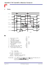
Page 106: ...S R _W asserted to _DS asserted Data out valid to _DS asserted _AS _DS negated to data out invalid min 10ns 80ns 10ns 0ns 0ns 0ns 50ns 20ns 15ns 0ns max 25ns 90ns 50ns A1 A7 _AS _LDS _UDS R _W _EDTACK _CXC CSx Recommended address lines address strobe lower upper data strobe read not write external data transfer acknowledge _CXC CS0 to _CXC CS7 Assert _EDTACK with CSx and _UDS _LDS and data valid d...

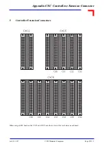
Page 107: ...CXC Controller eXtension Connector 4 Juli 23 1997 Page CXC 5 PEP Modular Computers 5 Controller Extension Connectors When using an 8TE board on the CXC5 and CXC8 note that a slot will be lost between each board ...

Page 108: ...Appendix CXC Controller eXtension Connector Page CXC 6 PEP Modular Computers Juli 23 1997 This page has been intentionally left blank ...

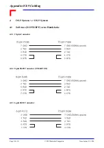
Page 109: ...mputers APPENDIX OS 9 CABLING This Appendix outlines the connection definitions of S 9 systems to various outside media 1 OS 9 System Terminal 1 1 Software XON XOFF or no Handshake 1 1 1 15 pin Connector on OS 9 Side 1 1 2 8 pin RJ45 Connector on OS 9 Side SMART I O ...

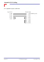
Page 110: ...Appendix OS 9 Cabling Page OS 2 PEP Modular Computers Novemeber 21 1996 1 1 3 6 pin RJ12 Connector on OS 9 Side ...

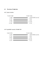
Page 111: ...x OS 9 Cabling 4 November 21 1996 Page OS 3 PEP Modular Computers 1 2 Hardware Handshake Set Terminal to CTS DTR Handshake 1 2 1 15 pin Connector on OS 9 Side 1 2 2 8 pin RJ45 Connector on OS 9 Side SMART I O ...

Page 112: ... OS 4 PEP Modular Computers Novemeber 21 1996 2 OS 9 System PC 2 1 Software XON XOFF or no Handshake 2 1 1 15 pin Connector on OS 9 Side 25 pin Connector on PC Side 2 1 2 15 pin Connector on OS 9 Side 9 pin Connector on PC Side ...

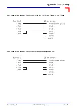
Page 113: ... OS 9 Cabling 4 November 21 1996 Page OS 5 PEP Modular Computers 2 1 3 8 pin RJ45 Connector on OS 9 Side SMART I O 25 pin Connector on PC Side 2 1 4 6 pin RJ12 Connector on OS 9 Side 25 pin Connector on PC Side ...

Page 114: ...x OS 9 Cabling Page OS 6 PEP Modular Computers Novemeber 21 1996 2 1 5 8 pin RJ45 Connector on OS 9 Side SMART I O 9 pin Connector on PC Side 2 1 6 6 pin RJ12 Connector on OS 9 Side 9 pin Connector on PC Side ...

Page 115: ...2 2 Hardware Handshake Select RTS CTS Handshake on the PC Side 2 2 1 15 pin Connector on OS 9 Side 25 pin Connector on PC Side 2 2 2 15 pin Connector on OS 9 Side 9 pin Connector on PC Side ...

Page 116: ...9 Cabling Page OS 8 PEP Modular Computers Novemeber 21 1996 2 2 3 8 pin RJ45 Connector on OS 9 Side SMART I O 25 pin Connector on PC Side 2 2 4 8 pin RJ45 Connector on OS 9 Side SMART I O 9 pin Connector on PC Side ...

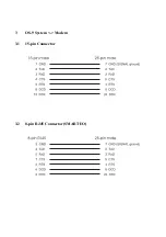
Page 117: ...3 OS 9 System Modem 3 1 15 pin Connector 3 2 8 pin RJ45 Connector SMART I O ...

Page 118: ... 9 Cabling Page OS 10 PEP Modular Computers Novemeber 21 1996 4 OS 9 System OS 9 System 4 1 Software XON XOFF or no Handshake 4 1 1 15 pin Connector 4 1 2 8 pin RJ45 Connector SMART I O 4 1 3 6 pin RJ12 Connector ...

Page 119: ...4 2 Hardware Handshake 4 2 1 15 pin Connector 4 2 2 8 pin RJ45 Connector SMART I O ...

Page 120: ...Appendix OS 9 Cabling Page OS 12 PEP Modular Computers Novemeber 21 1996 This page has been intentionally left blank ...

Reviews: