Model 1011
Installation and Operation Manual
12
Par
t No
. 51
2083 Dra
wing No
. 1
29-0205a 03/09
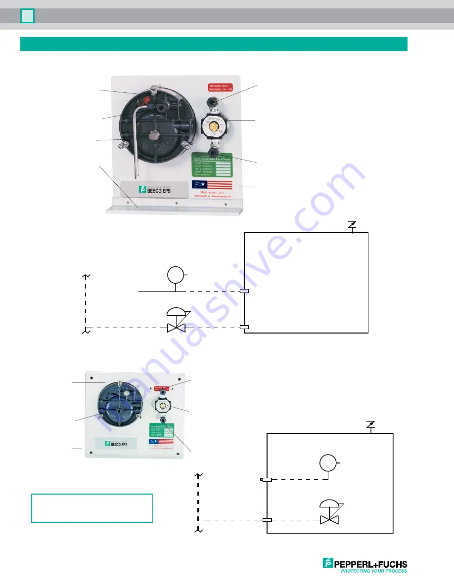
Tubing Connection Diagrams
LH, RH, TM, BM & FM Configuration Connection Points & Pneumatic Diagram
PM Configuration Connection Points & Pneumatic Diagram
HELPFUL HINT
Pneumatic connections are bolded.
Protected enclosure
Optional enclosure
protection vent
System
supply
Venturi
orifice
Inlet
Enclosure
pressure gauge
Regulator
Sintered
vent
Reference
Supply
Enclosure reference
bulkhead fitting
Enclosure supply
bulkhead fitting
Enclosure
pressure
gauge
Enclosure
reference
inlet
Venturi
orifice
Mounting
bracket
System
supply
inlet
Enclosure
pressure
control
regulator
Enclosure
supply
outlet
Mounting
plate
Top Mount Configuration
Enclosure
pressure
gauge
Atmospheric
reference
inlet
Mounting
plate
Optional enclosure
protection vent
Protected enclosure
System
supply
inlet
Enclosure
pressure
control
regulator
Enclosure
supply
outlet
System
supply
Inlet
System supply
bulkhead
Atmospheric
reference
bulkhead
Supply
Reference
Regulator
Enclosure
pressure gauge
Sintered
vent


