background image

PROCESS AUTOMATION

Manual

BARCON

Hydrostatic Pressure Transmitter LHC

Process Pressure Transmitter PPC

Summary of Contents for BARCON

Page 1: ...PROCESS AUTOMATION Manual BARCON Hydrostatic Pressure Transmitter LHC Process Pressure Transmitter PPC ...

Page 2: ...of the Electrical Industry as published by the Central Association of the Elektrotechnik und Elektroindustrie ZVEI e V v including the supplementary clause Extended reservation of title We at Pepperl Fuchs recognise a duty to make a contribution to the future For this reason this printed matter is produced on paper bleached without the use of chlorine ...

Page 3: ...nterface unit 7 4 1 3 Display unit 8 4 2 Function 9 4 2 1 Functions of devices without displays 9 4 2 2 Functions of devices with displays 9 4 2 3 Functions of devices with HART communication 10 4 3 Installation examples 11 5 Technical data 13 5 1 Physical input values 13 5 2 Physical output values 13 5 3 Construction 14 5 4 Auxiliary power 15 5 5 Ambient conditions 15 5 6 Process conditions 15 5 ...

Page 4: ... 8 3 The programming mode 30 8 4 Default data factory setting 30 8 5 Main menu 31 8 5 1 Main menu display 31 8 5 2 Main menu calibration of zero and span with without pressure 34 8 5 3 Main menu output 35 8 5 4 Main menu evaluation 36 8 5 5 Main menu language 38 8 5 6 Main menu service 39 9 Operation of devices with HART communication 40 9 1 HART connection options 40 9 1 1 Connection HART Hand he...

Page 5: ... 06 21 7 76 0 USA 330 4 25 35 55 Singapore 7 79 90 91 Internet http www pepperl fuchs com Date of Issue 15 12 2000 3 10 Dismantling packing and re packing 53 11 Guarantee and service 54 11 1 Guarantee conditions 54 11 2 Diagnostics and service 54 12 Appendix 55 12 1 Model number key 55 12 2 Dimensional drawings 57 12 3 Glossary 60 12 4 Units of pressure measurement 61 ...

Page 6: ...anufacturer of the product Pepperl Fuchs GmbH D 68301 Mannheim operates a certificated quality assurance system in accordance with ISO 9001 2 Symbols used in this document An appropriate declaration of conformity can be demanded from the manufacturer This symbol warns of danger If this instruction is not heeded there is a danger of the injury or death of personnel and damage to property or even it...

Page 7: ... and accident prevention regulations as well as the following safety instructions in this operating manual when working with the pressure transmitters Do not carry out any operation on the equipment unless it is described in the following instructions The connection of the devices and maintenance work under power must only be carried out by a qualified electrical specialist If faults cannot be eli...

Page 8: ...d PPC can be used in level control as well as pressure measurement in process applications A variety of process connections measurement ranges electronic interfaces and display options offer a product for a wide range of applications 4 1 Construction The pressure transmitters consists of a pressure sensor a control interface unit and a housing cover with optional display Different modular configur...

Page 9: ...another based on their ranges and the types of media touching materials Different versions of process connections can be selected for a wide range of application conditions The three main designs of pressure transmitters used in process applications are rod type rope type and externally mounted 4 1 2 Control interface unit The control interface unit contains the terminal compartment and the keypad...

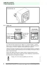
Page 10: ...t of measure can be selected by the operator Additional information is displayed in lines 2 and 3 16 segment display The operator can enter commands in the programming mode on the display unit by means of menu driven clear text prompts Devices with displays clearly offer a higher number of programming and control interface options These options include alarm status dampening signal inversion tank ...

Page 11: ...default values see section 7 6 Mounting correction of the sensor beginning with software version 1 04 see section 7 4 4 2 2 Functions of devices with displays Optional units of measure for measured values mbar bar psi mA m mm WS see section 8 5 1 Volume related unit measured value adjustable l kg m gal lb see section 8 5 1 Temperature and Min Max values shown in display see section 8 5 1 Nominal p...

Page 12: ...ng integration of output signal 0 s 40 s see section 9 2 5 Inversion of the output current signal see section 9 2 5 Alarm output current value setting 3 6 mA or 21 mA see section 9 2 5 Setting the limits of the output signal see section 9 2 5 Mounting correction of the sensor see section 9 2 7 Reset functions see section 9 2 7 Password activation see section 9 2 5 Measuring circuit test function s...

Page 13: ...e measured pressure is provided as a height proportion or level control signal The pressure is measured using absolute against a vacuum or relative against external or air pressure measurement depending on the type of sensor selected Level control Level control Externally mounted Combined pressure and head pressure with front flat diaphragm are measured by two externally mounted pressure transmitt...

Page 14: ...uring range selected The pressure is either measured as an absolute value relative to a vacuum or as a relative value relative to atmospheric pressure Process pressure measurement Process pressure measurement Used to measure pressure of liquids Used to measure container pressure or gases in pipelines Process pressure measurement Process pressure measurement Installed behind feed pumps for Units in...

Page 15: ...0 10 0 6 0 201 35 35 0 16 0 536 80 80 0 40 0 1340 80 400 0 100 0 3350 200 800 0 250 0 8375 500 1200 0 600 0 20100 1200 2400 0 1000 0 33500 1500 3000 1 0 33 5 0 2 2 1 0 6 33 5 20 1 10 10 1 3 33 5 100 5 35 35 1 5 33 5 167 5 35 35 1 15 33 5 502 5 80 80 only relative pressure Do not exceed the nominal pressure Output signal 4 mA 20 mA Non Linearity KA of span Linearity including hysteresis and repeata...

Page 16: ...g rod and rope versions LHC Process connections for the externally mounted version G1 A 1 NPT G1 A 1 NPT LHC Process connections for rod or rope version G1 A in stainless steel 1 4571 1 NPT in stainless steel 1 4571 Milk pipe DN40 Triclamp 2 Flange DN50 PN40 Flange ANSI 2 150 psi others upon request PPC process connections G A Manometer connection DIN 16288 NPT G B O ring flush with front face G 1...

Page 17: ...cal protection methods Reverse polarity protected lightning protection short circuit protection Power supply 12 V 36 V 12 V 30 V external versions Ambient Temperature 40 C 85 C 20 C 70 C with display Storage Temperature 40 C 85 C 35 C 80 C with display Climate Class D per DIN IEC 654 1 Protection class per EN 60529 IP65 IP67 upon request EMC per EN 50081 2 EN 50082 2 NAMUR NE 21 A maximum cleaning...

Page 18: ...ments of EN 50014 1992 EN 50020 1994 and EN 50284 1997 Ignition protection method explosion group EEx ia IIC EC Design Test Certification DMT 99 ATEX E070 Device markings II 1 2 G EEx ia IIC T6 T4 Ambient temperature 40 C Ta 60 C for T6 40 C Ta 70 C for T4 Nominal values terminal V1 plug Pin1 Pin 2 Temperature of medium Pressure range externally mounted version PPCM externally mounted version LHCM...

Page 19: ...All information on approvals and certification can be found under www pepperl fuchs com Approvals Certification All information on approvals and certification can be found under www pepperl fuchs com Ignition protection method explosion group EEx ia IIC EC Design Test Certification DMT 99 ATEX E090 U Device markings II 2 G EEx ia IIC T6 T5 T4 Ambient temperature 40 C Ta see EC Design Test Certific...

Page 20: ...ermany 06 21 7 76 0 USA 330 4 25 35 55 Singapore 7 79 90 91 Internet http www pepperl fuchs com Date of Issue 15 12 2000 18 5 8 Identification plates Pressure transmitter LHC non external version Pressure transmitter LHC external version Process pressure transmitter PPC non external version Display EMP o o o oP o o o o DMT 99 ATEX 090 U II 2 G EEx ia IIC T4 T6 ...

Page 21: ...Installation using welding support Insert a filler piece a pressure transmitter dummy into the welding support Weld the support into the container pipe wall section weld process Remove the filler piece Install the pressure transmitter in the welding support 6 2 Display unit upgrades The display unit can be easily upgraded at any time Remove the housing cover and the support cable Attach the suppor...

Page 22: ... the housing of the display unit in order to be able to read the display from above when the pressure transmitter is installed in an upright position Loosen the 4 internal hexagonal screws Lightly lift off the housing with the display unit Carefully turn the housing through 180 Re tighten the screws When attaching the indicator unit make sure that the connection power supply cable and the support ...

Page 23: ... unit a transmitter power supply or by means of a PLC connection PEPPERL FUCHS suggests using a design with integrated lightning protection for preventing damage due to voltage spikes Terminal configuration Terminal connection for power supply 2 wire transmitter 4 mA 20 mA Negative Postive Ground I Test circuit connect the ampere meter between terminals and I V1 plug optional Pin 1 positve Pin 2 n...

Page 24: ...Issue 12 01 2001 22 6 5 Pressure compensation when using a relative pressure sensor A Goretex diaphragm is used to compensate for the atmospheric pressure under the IP65 protection method A special cable with capillaries for relative pressurization is used for protection method IP67 Please consider that all versions with aluminium housing and conduit connection version EMC require a protection cla...

Page 25: ...ner with without pressure Integration time Mounting correction of the sensor beginning with software version 1 04 Reset to manufacturer s defaults 7 2 Key functions An error signal is caused by a current surge 21 mA or 3 6 mA 5 sec when the zero point or span setting fall outside of the sensor s nominal pressure range during adjustments with existing pressure No values are stored The keypad become...

Page 26: ...t the transmitter diaphragm before calibration Ensure that the pressure to be used as the span end point P 100 is present at the transmitter diaphragm A change in the zero point has no effect on the calibrated span However if the span end point is higher than the peak value of the sensor s nominal pressure range the span end point is fixed at this peak value and the span is reduced accordingly A c...

Page 27: ...ressure transducer with 0 mbar 400 mbar nominal pressure needs to be programmed The liquid s surface with a density of 1 is 1 m above the diaphragm at the zero point producing a pressure of 100 mbar This means that the device s current value must be set to 8 mA when performing a dry empty calibration 7 4 2 Span calibration Determine the hydrostatic pressure of the liquid s surface which correspond...

Page 28: ...sted span However if the span end point is higher than the peak value of the sensor s nominal pressure range then the span end point is fixed at this peak value and the span is reduced accordingly A change in the span setting has no effect on the zero point The zero point and span end point must fall within the sensor s nominal pressure range A test correction of the zero point is suggested after ...

Page 29: ...ing correction of the sensor The position of the measuring cell is entered by simultaneously depressing 2 sec the zero and esc buttons 7 5 Integration time dampening adjustment The following integration time settings can be used 0 1 5 20 and 40 sec The sensor s measured values can then be averaged using the adjusted integration time Mounting correction of the sensor 049 DS D Calibration Value Func...

Page 30: ...om Date of Issue 15 12 2000 28 7 6 Reset to default All default data settings are restored by simultaneously pressing the zero esc and the ok buttons for 2 sec see section 8 4 Calibrated special measurement ranges i e 4 bar on a 6 bar transmitter can be adjusted by factory pre setting A reset to default will reset the sensor back to its nominal range i e 6 bar The factory pre setting gets lost Res...

Page 31: ... 1 The display In order to program the device remove the display with a screwdriver and re attach it to the housing as shown in the diagram below 8 2 Key functions Button Functions Main menu Sub menu Edit functions back to previous menu option back to previous menu option increase value forward to next menu option forward to next menu option decrease value back to value display without saving back...

Page 32: ...nction are stored A change in the starting measurement zero point has no effect on the measurement span Likewise a change in the span has no effect on the starting measurement An error signal occurs when the zero point or span settings fall outside of the sensor s nominal pressure range during calibration with pressure Nothing is saved Function Default Display Unit of measurement Line 1 Line 2 Lin...

Page 33: ...nu display The density of a medium must be entered to calculate the correct fill level when displaying or adjusting the level in hight units e g mm m feet inch see section 8 5 4 For volume based units it is necessary to enter the reference value 100 0 0 value range 0 3000 0 CALIBRATION RANGE DISPLAY OPTIONS CALIBRATION RANGE OUTPUT DEFINITION EVALUATION FUNCTION LANGUAGE OPTIONS SERVICE FUNCTIONS ...

Page 34: ...W 2 P RANGE Second line shows measured value in Second line remains empty Second line shows minimum values Second line shows minimum Temp in o C Second line shows minimum Temp in o F Second line shows maximum values Second line shows maximum Temp in o C Second line shows maximum Temp in o F Second line shows current Temp in o C Second line shows current Temp in o F Second line shows present curren...

Page 35: ...TURE in o F ROW 3 MAX VALUE ROW 3 MEASUREMENT ROW 3 TEMPERATURE TEMPERATURE in o C TEMPERATURE in o F TEMPERATURE in o C TEMPERATURE in o F ROW 3 TEMPERATURE ROW 3 CURRENT in mA ROW 3 P RANGE Third line shows measured value in Third line remains empty Third line shows minimum values Third line shows minimum Temp in o C Third line shows minimum Temp in o F Third line shows maximum values Third line...

Page 36: ...d before or after making an adjustment without pressure dry adjustment see section 8 5 6 The sensor must therefore be placed in the reference position for the measurement installation site without pressure on the diaphragm An adjustment of the physical units takes place without pressure On process pressure sensors 1 bar xx bar the value shown on the display is al ways related to the physical press...

Page 37: ...RSION OUTPUT ALARM ERROR OUTPUT LIMITS OUTPUT CURRENT OFFSET LIMITS LIMITS The current runs between 4 and 20 mA Alarm condition when limits are reached It is necessary to restart device by using reset or by shutting down power see 8 5 6 Damping 40 s active Damping 20 s active Damping 5 s active Damping 1 s active Output is inverted 20 mA 4 mA or reverted 4 mA 20 mA Alarm at 3 6 mA downscale Alarm ...

Page 38: ...ATION REF TABLE REF POINT INSERT REF POINT DELETE INSERT INSERT DELETE DELETE DELETE The level value and volume value always be adjusted or verified in order to store a value pair TABLE EDIT TABLE ACTIVATE EVALUATION LINEAR LINEAR ACTIVATE EVALUATION DENSITY DENSITY Entry of a new value pair for the table used in tank linearization Entry of the level in Entry of the associated volume in It is poss...

Page 39: ...ure to 4000 mm in order to prevent a 4000 mm level tank from being overfilled Please check the following if Wrong Entry appears in the Evaluation menu Whether or not more than 32 value pairs are entered in the table for tank linearization please note P 0 and P 31 are fixed at 0 and 100 respectively Whether or not an existing height value was tried to be stored again Please enter correct values A c...

Page 40: ...15 12 2000 38 8 5 5 Main menu language On devices with HART communication the language cannot be selected The display language is always English MAIN MENU LANGUAGE LANGUAGE OPTIONS SPRACHE DEUTSCH LANGUE FRANCAIS LANGUAGE ENGLISH All displays will be in German All displays will be in English All displays will be in French LINGUA ITALIANO All displays will be in Italian LENGUA ESPANOL All displays ...

Page 41: ...IMER RESET MIN MAX VALUES All values are reset to the factory setting see 8 4 SERVICE PASSWORD PASSWORD DE ACTIVE ENTRY CIRCUIT TEST Hrs TOTAL Hrs CALIBRATE Hrs RESET Hrs SENSOR RESET ALL RESET ALARM The set current value is used as the test signal until the esc button is pressed Total number of operating hours Number of hours since the last calibration Number of hours since the last system reset ...

Page 42: ...er or RPI system from Pepperl Fuchs 9 1 1 Connection HART Hand held terminal The LHC and PPC pressure transducers can be operated with the standard menus of the HART Hand held terminal A special DD Device Description is not required A specified DD can be ordered from Pepperl Fuchs The terminal resistance in the loop must be at least 250 Ω A description of the HART Hand held terminal and its operat...

Page 43: ...modem for operation via a PC The HART modem connects the pressure transmitter with HART functionality to the RS232 C serial interface of a personal computer This enables the pressure transmitter to be remotely operated using the PACTware program A corresponding HART modem can be ordered from Pepperl Fuchs PLC LHC PPC Transmitter power supply e g KFD2 STC3 Ex 1 4 mA 20 mA 4 mA 20 mA 250 Ω Ex area S...

Page 44: ...er supply signal line voltage source are less than 250 Ω a minimum resistance of 250 Ω must be installed in the power supply line The sum of the internal capacitances and inductances of the components used must not exceed the highest permissible values of the ia IIC circuit Please take into consideration the intrinsic safety data see section 5 7 and note the permissible cable length at devices wit...

Page 45: ...ith the requested device driver FDT can be ordered from Pepperl Fuchs An integration in other HART management systems or FDT management systems is possible The description of the PACTware program and the instruction can be found in the software manual 9 2 1 Register card Device info Device information is shown in the fields on the register card Device info This information cannot be changed 9 2 2 ...

Page 46: ...f measuring point Measuring point description Information about measuring point Parameterization dated on Date of last parameterization Units measured values Units of the measured values mbar bar PSI at kg cm mA mm m inch feet Pa kPa Mpa mmWS mmHG Volume reference units l kg t m gal lb Reference value The reference value of the volume based units is only active when the volume units have been acti...

Page 47: ... of temperature in F maximum value of temperature in F Temperature in C Temperature in F Current in mA P Range 9 2 4 Register card Parameter calibration Measured value cyclic measurement Display of the current measured value for the calibration with pressure Automatically updated Calibration with pressure The calibration with pressure is only possible when the cyclic measurement is activated Setti...

Page 48: ...d to the associated output current signal If the pressure lies outside the nominal pressure range of the sensor a fault signal results The value is then not saved A change in the zero point has no effect on the set span However if due to a change in the zero point the span end point represents a value in excess of highest value of the nominal pressure range of the sensor the span end point remains...

Page 49: ...the sensor are averaged over the set integration time The following integration times can be set 0 1 5 20 and 40 sec Inverted output The output signal is inverted or de inverted inverted 20 4 mA de inverted 4 20 mA Alarm Data current values set for alarm messages 21 0 mA upscale or 3 6 mA downscale Current output limits Data ranges in which the current output is set 3 8 20 5 mA If the measuring ra...

Page 50: ...t between values of height and volume Table The values in the table provide a linear relationship between height and volume For measurements in a tank values of height level are input and a volume is assigned to each value These pairs of values are used to determine the linear relationship and to assign the 4 mA 20 mA output signal to values of tank volume P 0 and P 31 are fixed at 0 and 100 Check...

Page 51: ...in both interrogation fields If a password is activated changes in the settings for devices with a display can only be made on entering the password On devices without a display no values can be changed on the device Activation of mounting correction The mounting correction is carried out The sensor must first be in the mounting position and be unpressurised Elapsed hours meter Display only STD TO...

Page 52: ... During online operation the measured value is output as a current 9 2 9 Menu item Measuring value You can open the measuring value window under Device data in the Measuring value menu item or in the Context menu right mouse button for the device that is selected in the navigation window project view Special measuring ranges such as 4 bar with a 6 bar pressure transmitter are achieved by means of ...

Page 53: ...menu item or in the Context menu right mouse button for the device that is selected in the navigation window project view This display provides information on the variation of the measured value with time recorder function The scale can be changed by clicking on the time or the scaling axis 9 2 11 Menu item Burst mode You can open the burst mode window under Device data in the Burst mode menu item...

Page 54: ... pressure value output current to the master on a cyclic basis Current value and current Pressure temperature and current 9 2 12 Menu item Diagnosis You can open the diagnosis window under Device data in the Diagnosis menu item or in the Context menu right mouse button for the device that is selected in the navigation window project view Possible errors and their short description are indicated se...

Page 55: ...of Issue 15 12 2000 53 10 Dismantling packing and re packing If the device is to be stored for later re use the device should be packed in such a way as to ensure protection from shock Optimum protection is afforded by the original packaging Disposal Electronic waste is classified as special refuse Please observe local guidelines and regulations when disposing of devices that are no longer service...

Page 56: ...e unauthorized They will cause the loss of all warranty claims If the fault cannot be corrected the device should be taken out of operation and stored to prevent re installation Repairs should only be performed by the manufacturer All other repairs or alterations are unauthorized Error code Error Error correction measures E00 ROM error Return device to manufacturer E01 Power supply error Test powe...

Page 57: ...s steel 1 4571 N 3 1 NPT with diaphragm stainless steel 1 4571 G 5 G 1 1 2 A with diaphragm stainless steel 1 4571 N 5 1 1 2 NPT with diaphragm stainless steel 1 4571 Process connections for rod and rope type G 5 G 1 1 2 A stainless steel 1 4571 N 5 1 1 2 NPT stainless steel 1 4571 M 4 Milk pipe DN40 T 2 Triclamp 2 F 1 Flange DN50 PN40 A 2 Flange ANSI 2 150 PSI Material in contact with medium S St...

Page 58: ... 1 G 1 2 manometer connection DIN 16288 N 1 1 2 NPT O 1 G 1 2 with O ring 1 6 bar O 3 G 1 with O ring 1 6 bar Material in contact with medium S Stainless steel 1 4571 Sensor filling medium 1 Standard filling 2 Filling for food applications Housing and cable glands P Plastic with cable connection M20 x 1 5 Electrical output I 2 2 wire 4 mA 20 mA 2 L 2 wire 4 mA 20 mA with OV protection I H 2 wire 4...

Page 59: ...pyright Pepperl Fuchs Printed in Germany Pepperl Fuchs Group Tel Germany 06 21 7 76 0 USA 330 4 25 35 55 Singapore 7 79 90 91 Internet http www pepperl fuchs com Date of Issue 29 11 2000 57 12 2 Dimensional drawings Hydrostatic pressure transmitter LHC mounting version approx 95 approx 95 ...

Page 60: ... Pepperl Fuchs Printed in Germany Pepperl Fuchs Group Tel Germany 06 21 7 76 0 USA 330 4 25 35 55 Singapore 7 79 90 91 Internet http www pepperl fuchs com Date of Issue 29 11 2000 58 Hydrostatic pressure transmitter LHC rod and rope version L Length acc customer specification approx 95 approx 95 ...

Page 61: ...330 4 25 35 55 Singapore 7 79 90 91 Internet http www pepperl fuchs com Date of Issue 29 11 2000 59 Pressure transmitter PPC mounting version with G B manometer connection Pressure transmitter PPC mounting version with G B and G1B O ring flush with front face approx 95 M20 x 1 5 86 20 3 3 SW27 ø6 ø17 5 G B 044 DS D 86 20 5 10 SW41 ø30 0 1 G1B 053 DS D 86 20 5 10 SW27 ø17 5 G B ...

Page 62: ...A 20 mA to 20 mA 4 mA Nom pressure range The operating pressure range for which the sensor was designed Parameterization Also configuration programming of the relevant parameters and the pressure measurement range specific to the application and measurement location Span The programmed pressure measurement range Span end point The highest pressure value of the programmed measurement span end point...

Page 63: ...SA 330 4 25 35 55 Singapore 7 79 90 91 Internet http www pepperl fuchs com Date of Issue 29 11 2000 61 12 4 Units of pressure measurement 1 atm atmospheres 760 mm Hg 760 Torr 1 033 kp cm 0 1013 MPa 1 Torr 133 3 Pa 1 kp mm 9 81 N mm 9 81 MPa 1 bar 0 1 MPa 33 5 feet of water 1 mbar 1 hPa Hektopascal 1 psi pound per square inch 6 895 x 10 Pa 1 Pa 1 0 x 105 bar 1 mmHG 1 333 mbar ...

Page 64: ...onable modifications due to technical advances Copyright Pepperl Fuchs Printed in Germany Pepperl Fuchs Group Tel Germany 06 21 7 76 0 USA 330 4 25 35 55 Singapore 7 79 90 91 Internet http www pepperl fuchs com Date of Issue 29 11 2000 62 ...

Page 65: ...onable modifications due to technical advances Copyright Pepperl Fuchs Printed in Germany Pepperl Fuchs Group Tel Germany 06 21 7 76 0 USA 330 4 25 35 55 Singapore 7 79 90 91 Internet http www pepperl fuchs com Date of Issue 29 11 2000 63 ...

Page 66: ...onable modifications due to technical advances Copyright Pepperl Fuchs Printed in Germany Pepperl Fuchs Group Tel Germany 06 21 7 76 0 USA 330 4 25 35 55 Singapore 7 79 90 91 Internet http www pepperl fuchs com Date of Issue 29 11 2000 64 ...

Page 67: ...of the Electrical Industry as published by the Central Association of the Elektrotechnik und Elektroindustrie ZVEI e V v including the supplementary clause Extended reservation of title We at Pepperl Fuchs recognise a duty to make a contribution to the future For this reason this printed matter is produced on paper bleached without the use of chlorine ...

Page 68: ...rldwide Headquarters 01 23 42563 7 89 4 3 34 6 89 4 3 34 6 66 http www pepperl fuchs com e mail pa info de pepperl fuchs com The Pepperl Fuchs Group USA Headquarters 466 7 88623 7 556 8 5 556 8 8463 e mail sales us pepperl fuchs com Asia Pacific Headquarters 2 5998 7 4 3 39 96 9 4 2 35 4 53 e mail sales sg pepperl fuchs com Service Area 96 778 11 00 03 ...

Reviews: