20
16-11
16
H-System – Isolated Barriers and Termination Boards for HIMA
Product Specifications
2.4
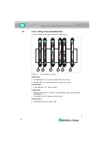
Color Coding of the Isolated Barriers
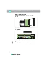
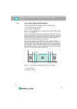
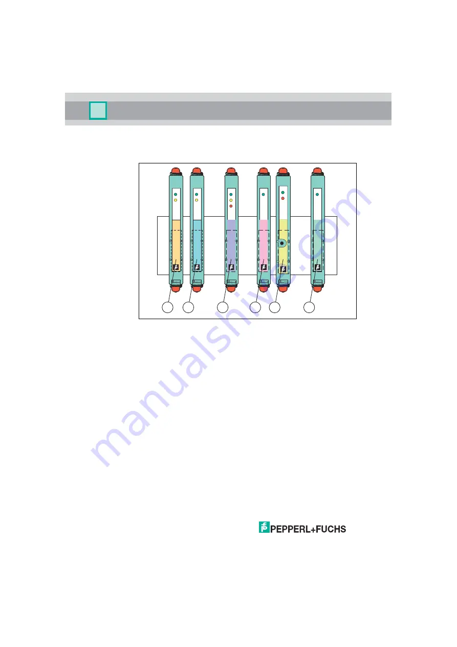
The color coding of the devices has the following meaning:
Figure 2.14
Color identification of devices
Digital Input
• Orange identifier (1) for switch amplifiers with a relay output
• Blue identifier (2) for switch amplifiers with a transistor output
Digital Output
• Purple identifier (3) for solenoid drivers
Analog Input
• Magenta identifier (4) for transmitter power supplies, measuring transmitters,
and repeaters
• Yellow identifier (5) for temperature converters
Analog Output
• Green identifier (6) for current drivers
PWR
HiC
2841
1 ch
Switch
Amplifier
CH1
FAULT
STATUS/
PWR
HiC
2821
1 ch
Switch
Amplifier
CH1
FAULT
STATUS/
2
1
PWR
HiC
2873
1 ch
Solenoid
Driver
STATUS
FAULT
1 ch
Temp.
Conv.
2081
PWR
FAULT
HiC
PROG
PWR
HiC
2031
1 ch
Current
Driver
PWR
HiC
2025
1 ch
Transm.
Power
Supply
5
6
3
4


