H-System – Isolated Barriers and Termination Boards for HIMA
Installation
20
16-11
25
3.3
Connection
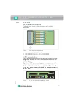
Connecting the Field Side
Connect the field devices to the termination board via the spring terminals.
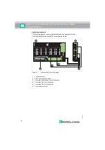
Connecting the Power Supply and Fault Indication Output
Connect the power supply and fault indication output via the spring terminals.
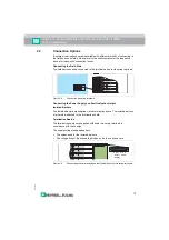
Connecting the Control Side
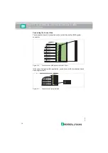
Connect the termination board on the control side via the following connection
options:
• HIMA sytem connector, 96-pin
• HART plug, if applicable
• Spring terminals, if applicable
Danger!
Danger to life from electric shock
Absent or insufficient insulation can result in electric shock.
Only connect supplies that provide protection against electric shock (e. g. SELV
or PELV).
Danger!
Danger to life from incorrect installation
Incorrect installation of cables and connection lines can compromise the function
and the electrical safety of the device.
• Observe the permissible core cross-section of the conductor.
• When using stranded conductors, crimp wire end ferrules on the conductor
ends.
• Use only one conductor per terminal.
• When installing the conductors the insulation must reach up to the terminal.
• Observe the tightening torque of the terminal screws.
Danger!
Explosion hazard from wrong separation distances
If you do not observe the minimum separation distance between 2 intrinsically
safe circuits, this can lead to added currents or voltages. This can result in a
current/voltage flashover generating sparks. The sparks can ignite the
surrounding potentially explosive atmosphere.
Ensure you observe all separation distances between 2 adjacent intrinsically safe
circuits according to IEC/EN 60079-14.

