background image

IDENT-I • IVI-KHD2-4HB5, IVI-KHA6-4HB5

Operation with the INTERBUS

Subject to reasonable modifications due to technical advances.

Copyright Fuchs, Printed in Germany

Fuchs Group • Tel.: Germany (06 21) 7 76-0 • USA (330) 4 25 35 55 • Singapore 7 79 90 91 • Internet http://www.pepperl-fuchs.com

D

a

te

 of

 is

su

e

1

9.

07

.2

0

0

1

29

7.2.3

Detailed description of the commands

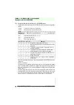
Fixcode commands

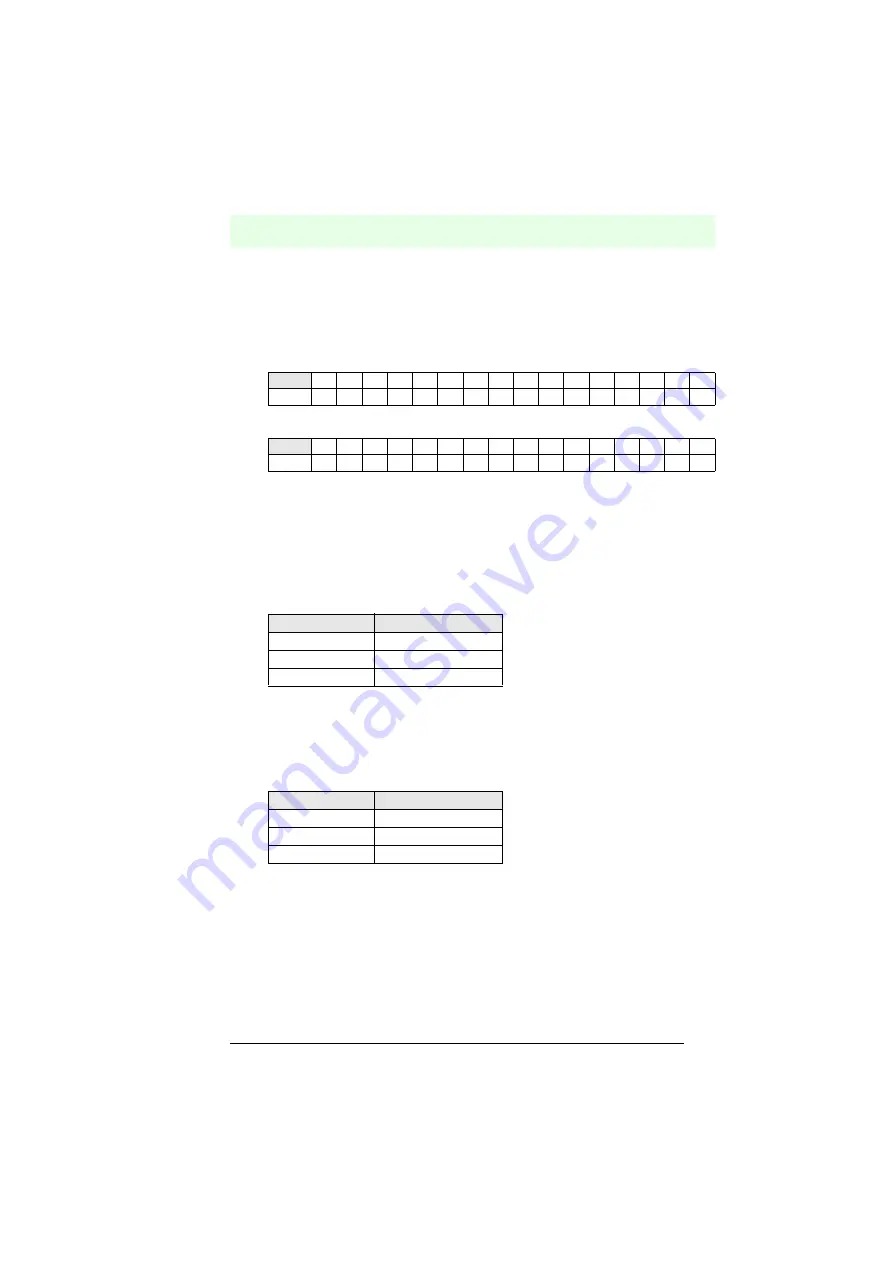
In the case of the fixcode SF, AF and BF, the following data is obtained as a response 
in words 2 and 3:

Word 2:

Word 3:

C28...C1 : 28 bit code carrier fixcode

The word start address in Word 1 is ignored.

Data carrier write commands

On writing, in Words 2 and 3, the data to be written is transferred to the control inter-
face unit. The content of Words 2 and 3 is not defined in the response.

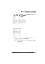
Valid word starting addresses in Word 1 are summarised in the following table:

Data carrier read commands

On a read command, the content of Words 2 and 3 are ignored by the control interface 
unit. The response contains the read data.

Valid word starting addresses in Word 1 are summarised in the following table:

Bit No.

15

14

13

12

11

10

9

8

7

6

5

4

3

2

1

0

-0

0

0

0 C28 C27 C25 C25 C24 C23 C22 C21 C20 C19 C18 C17

Bit No.

15

14

13

12

11

10

9

8

7

6

5

4

3

2

1

0

C16

C15

C14 C13 C12 C11 C10 C9 C8 C7 C6 C5 C4 C3 C2 C1

Data carrier type

Address range (hex)

1DC-1k

0000 ... 003F

IMC40-64k

0000 ... 0FFF

IMC40-356k

0000 ... 3FFF

Data carrier type

Dress range (hex)

1DC-1k

0000 ... 003F

IMC40-64k

0000 ... 0FFF

IMC40-356k

0000 ... 3FFF

Summary of Contents for IVI-KHA6-4HB5

Page 1: ...FACTORY AUTOMATION M M M MA A A AN N N NU U U UA A A AL L L L IVI KHD2 4HB5 IVI KHA6 4HB5 CONTROL INTERFACE UNIT FOR INTERBUS ...

Page 2: ... of the Electrical Industry as published by the Central Association of the Elektrotechnik und Elektroindustrie ZVEI e V including the supplementary clause Extended reservation of title We at Pepperl Fuchs recognise a duty to make a contribution to the future For this reason this printed matter is produced on paper bleached without the use of chlorine ...

Page 3: ...n 10 4 4 LED displays 11 4 5 Structure and operation 11 4 6 Accessories product family 12 5 Installation 13 5 1 Storage and transport 13 5 2 Unpacking 13 5 3 Mounting 14 5 3 1 Mounting on a top hat rail 14 5 3 2 Wall mounting 15 5 4 Electrical connection 15 5 4 1 Equipment connection 16 5 4 2 Read head cable lengths 19 5 4 3 Special connection information for the INTERBUS cable 20 5 5 Disassembly ...

Page 4: ... Short Description 37 11 2 Setting the INTERBUS S interface 37 11 3 Used hardware 37 11 4 Program 38 11 4 1 Logical addressing on startup 38 11 4 2 Cyclic program OB1 38 11 4 3 DB 10 Ident Code list 39 11 4 4 DB 11 bus segment list 40 11 4 5 DB 12 IN address list 41 11 4 6 DB 13 Out address list 42 11 4 7 BB1 image block 43 11 5 Blocks 43 11 5 1 OB1 structure 43 11 5 2 OB20 OB 21 OB 22 structure 4...

Page 5: ...www pepperl fuchs com Date of issue 27 07 2001 3 1 Declaration of Conformity The control interfaces IVI KHD2 4HB5 and IVI KHA6 4HB5 have been developed and produced in accordance with the applicable European standards and directives The manufacturer of the product Pepperl Fuchs GmbH in D 68301 Mannheim pos sesses a certified quality assurance system in accordance with ISO 9001 A corresponding decl...

Page 6: ...rmity Subject to reasonable modifications due to technical advances Copyright Pepperl Fuchs Printed in Germany Pepperl Fuchs Group Tel Germany 06 21 7 76 0 USA 330 4 25 35 55 Singapore 7 79 90 91 Internet http www pepperl fuchs com Date of issue 27 07 2001 4 ...

Page 7: ...e 7 79 90 91 Internet http www pepperl fuchs com Date of issue 27 07 2001 5 2 General Information This symbol warns the user of possible danger Failure to heed this warning can lead to personal injury or death and or damage to equip ment This symbol warns the user of a possible failure Failure to heed this warning can lead to total failure of the equipment or any other connec ted equipment This sy...

Page 8: ...on Subject to reasonable modifications due to technical advances Copyright Pepperl Fuchs Printed in Germany Pepperl Fuchs Group Tel Germany 06 21 7 76 0 USA 330 4 25 35 55 Singapore 7 79 90 91 Internet http www pepperl fuchs com Date of issue 27 07 2001 6 ...

Page 9: ...ed Device failure or breakdown of a read write head can be de tected and indicated by the master unit The protection of operating personnel and the system against possible danger is not guaranteed if the control interface unit is not operated in accordance with its intended use The device IVI KHD2 4HB5 IVI KHA6 4HB5 may only be operated by appropriately qualified personnel in accordance with this ...

Page 10: ...ect to reasonable modifications due to technical advances Copyright Pepperl Fuchs Printed in Germany Pepperl Fuchs Group Tel Germany 06 21 7 76 0 USA 330 4 25 35 55 Singapore 7 79 90 91 Internet http www pepperl fuchs com Date of issue 19 07 2001 8 ...

Page 11: ...1 terminal adapter 1 CD ROM including manuals as PDF files german english and the unit descrip tion for the commissioning software 4 2 Areas of application Bus systems especially the INTERBUS enable the amount of interconnection ca bling to be reduced and allow a greater exchange of data over long distances The control interface unit IVI KHD2 4HB5 IVI KHA6 4HB5 with an INTERBUS connection is unsur...

Page 12: ...ication and data transmission with an INTERBUS master unit Figure 4 1 Function of the control interface unit IVI KHD2 4HB5 IVI KHA6 4HB5 in the IDENT I System V inductive identification system It is possible to connect up to 4 read heads to a single IVI KHD2 4HB5 IVI KHA6 4HB5 unit The control interface unit operates as a passive device slave in the system bus Its use is therefore limited to the c...

Page 13: ...D2 4HB5 IVI KHA6 4HB5 is the link between the read write heads and the INTERBUS master PLC PC etc Two independently op erating microprocessors which are connected to each other via an interface cater for the data exchange between the read write heads and the INTERBUS master Figure 4 2 Block diagram of the IRI KHD2 4HB5 IVI KHA6 4HB5 control interface unit Both the supply voltage and the bus segmen...

Page 14: ...ly The IDENT I inductive identification system from Pepperl Fuchs offers many different options in combining the individual components Figure 4 3 Overview of the inductive identification system components Appropriate code carriers and read heads can be selected to suit installation require ments read distance and environmental conditions Further information on the inductive identification system w...

Page 15: ...umidity The original packaging offers optimum protection The ne cessary environmental conditions must also be satisfied see Technical Data 5 2 Unpacking Check that the contents are not damaged In case of damage notify the postal service or the forwarding agent and inform the carrier Check the contents of the package with respect to your order and the delivery docu ments for correct number of parts...

Page 16: ... 26 07 2001 14 5 3 Mounting 5 3 1 Mounting on a top hat rail As with all systems in K system housings from Pepperl Fuchs the control interface unit IVI KHD2 4HB5 IVI KHA6 4HB5 can be snapped onto the 35 mm standard top hat rail to DIN EN 50022 Figure 5 1 Mounting to the top hat rail to DIN EN 50022 Position the unit over the top edge of the top hat rail and press the bottom section of the housing ...

Page 17: ...four screws Simply extend the four outer brackets on the base of the unit The unit can then be easily screwed onto the wall through the holes in the brackets The screw pitch dimension is 90 mm max screw diameter M5 Figure 5 2 Wall mounting 5 4 Electrical connection Only qualified personnel are permitted to carry out work under voltage and make electrical connection to the mains Ensure that the cor...

Page 18: ...ew terminals Connect the read write heads and the supply voltage in accordance with the connec tion diagram and the labelled configuration of the terminals Figure 5 3 Connection diagram for the IVI KHD2 4HB5 IVI KHA6 4HB5 control interface unit Location of the connection terminals Figure 5 4 Assignment of connection terminals Reset Data reserved Reset Data reserved Reset Data reserved Reset Data r...

Page 19: ...N 6 Shield INTERBUS IN 7 supply voltage read head 1 negative 8 reserved 9 reserved 10 reserved 11 reserved 12 reserved 13 supply voltage read head 2 positive 14 direction read head 2 15 data read head 2 16 DO INTERBUS IN 17 DO INTERBUS IN 18 GND INTERBUS IN 19 supply voltage read head 2 negative 20 reserved 21 reserved 22 reserved 23 reserved 24 reserved 25 supply voltage read head 3 positive 26 d...

Page 20: ...of issue 26 07 2001 18 Assignment of the 9 pole Sub D plug and socket 4a 39 data read head 4 40 DO INTERBUS OUT 41 DO INTERBUS OUT 42 protective earth PE Shield INTERBUS OUT 43 supply voltage read head 4 negative 44 reserved 45 reserved 46 ground power supply 47 power supply 48 power supply PIN INTERBUS IN INTERBUS OUT 1 DO DO 2 DI DI 3 GND GND 4 reserved reserved 5 reserved reserved 6 DO DO 7 DI ...

Page 21: ...hat the attached terminal block can be used see Figure 5 5 Figure 5 5 Terminal block with connecting cables Read write head cable lengths up to 50 m or 100 m are possible if the following con ditions are satisfied up to 50 m read write head cable cross sectional area of at least 4 x 0 25 mm2 maximum resistance 78 Ohm km maximum capacitance 90 pF m e g LIYC11C Mukkenhaut Nusselt MUNFLEX C11Y up to ...

Page 22: ...is not the case e g a bus termi nal at the end of a branch the ring line in the affected unit must be closed This ring closure takes place automatically when the Sub D connections are used If the screw terminals on the IVI KHD2 4HB5 IVI KHA6 4HB5 are used to connect the bus line the rotary switch for the ring closure labelled S1 must be moved to the appropriate position see Figure 4 5 The ring clo...

Page 23: ...ength of leads Depending of the type of cable used and the extent of external noise sources the dis tance between two units can be up to 400 meters The total length of an INTERBUS system can extend up to 13 kilometers The number of units connected to the bus is limited to 512 cable construction 1 2 x 2 twisted pairs cross sectional area2 0 25 mm2 intrinsic impedance 100 130 W f 100 kHz capacitance...

Page 24: ... pepperl fuchs com Date of issue 26 07 2001 22 5 5 Disassembly packing and disposal Repacking The unit must be protected against humidity and shock when packing for later use The original packaging offers optimum protection Disposal Electronic waste can be hazardous Pay attention to local regulations when disposing of this unit The control interface unit IVI KHD2 4HB5 IVI KHA6 4HB5 does not contai...

Page 25: ...oject with an INTERBUS system a test system should first be constructed for the particular appli cation to test the transmission of data to the INTERBUS master Before proceeding with the commissioning ensure that no danger to the system can arise from the device e g due to uncontrolled proces ses Check again all connections before proceeding with the commissioning Prepare for the commissioning by ...

Page 26: ...ww pepperl fuchs com Date of issue 19 07 2001 24 6 2 Self test After switching on the supply voltage the control interface unit checks the internal me mory area with a self test If a RAM failure or ROM failure error occurs communi cation is not activated If no error is present the connection to the INTERBUS master is made automatically If the bus connection to the control interface unit is made th...

Page 27: ...idered as an extensive introduc tion to the INTERBUS For additional information reference should be made to the INTERBUS standard DIN 19258 and the relevant literature 7 2 Representation of commands and data on INTERBUS The IVI KHD2 4HB5 IVI KHA6 4HB5 control interface unit occupies 4 words each with 16 bits in the INTERBUS framework protocol in both communication directions It is therefore restri...

Page 28: ...C ICC 50 SF Security Flag ON OFF Data carrier can be read as a code carrier T2 1 Data carrier type When a code carrier is read the data carrier type is ignored Bit No 15 14 13 12 11 10 9 8 7 6 5 4 3 2 1 0 Designation B4 B3 B2 B1 DS SF T2 T1 N4 N3 N2 N1 K3 K2 K1 T B4 B3 B2 B1 Command Meaning 0 0 0 0 No command 0 0 0 1 SF Single Read Fixcode 0 0 1 0 AF Auto Read Fixcode 0 0 1 1 BF Buffered Auto Read...

Page 29: ... to 16 in future extensions K3 1 Head number T Toggle flag The toggle flag provides an indication for the user that the command has arrived at the control interface unit and is being has been processed On the first command T must equal 1 N4 N3 N2 N1 Number of words 0 0 0 0 reserved 0 0 0 1 1 0 0 1 0 2 0 0 1 1 reserved 0 1 0 0 reserved 0 1 0 1 reserved 1 1 1 0 reserved 1 1 1 1 reserved K3 K2 K1 Hea...

Page 30: ... counter is reset at the start of the command execution and then incre mented when the command has been fully executed in order to indicate the availabi lity of the status message and the read data if required In the buffered mode the execution counter is incremented on each successful read or write operation Word 0 Command Parameter Toggle flag Word 1 Status execution counter head number Bit No 1...

Page 31: ...d 3 the data to be written is transferred to the control inter face unit The content of Words 2 and 3 is not defined in the response Valid word starting addresses in Word 1 are summarised in the following table Data carrier read commands On a read command the content of Words 2 and 3 are ignored by the control interface unit The response contains the read data Valid word starting addresses in Word...

Page 32: ... 25 35 55 Singapore 7 79 90 91 Internet http www pepperl fuchs com Date of issue 19 07 2001 30 Device code software version message The device code identifier and software version are demanded via the command B4 B1 1111 The control interface unit transfers this data to Words 2 and 3 Word 2 Device code V5 for IVI KHxx 4HB5 Word 3 Software index ident bus software Bit 15 8 7 0 V 5 Bit 15 8 7 0 Index...

Page 33: ...com Date of issue 19 07 2001 31 8 Error Diagnostics LED error indication The status of the IVI KHD2 4HB5 IVI KHA6 4HB5 control interface unit is indicated on the Run Error LED The following figure illustrates the LED signals Figure 8 1 Flashing sequence of the Run Error LED Signal Meaning permanently green device ready for operation communication active once 0 5 s green 5 s red communication error...

Page 34: ... Subject to reasonable modifications due to technical advances Copyright Pepperl Fuchs Printed in Germany Pepperl Fuchs Group Tel Germany 06 21 7 76 0 USA 330 4 25 35 55 Singapore 7 79 90 91 Internet http www pepperl fuchs com Date of issue 19 07 2001 32 ...

Page 35: ...annel is used the parameter channel is not used Up to 4 read heads can be connected to the control interface unit The subscriber description for the INTERBUS software CMD tools is supplied ma king it possible to easily insert the control interface unit into the CMD subscriber da tabase Features INTERBUS remote bus subscriber Complete read write functionality via the INTERBUS 4 read write heads con...

Page 36: ...ies self opening apparatus terminals max cross sectional area 2 x 2 5 mm2 9 pin Sub D built in connector Housing material Makrolon 6485 Construction type K System 80 mm 4 TE Mounting snaps onto 35 mm standard rail according to DIN EN 50022 or screw mountable with 2 screws through pull out brackets in 90 mm spacing LED green Read write head active 4 LEDs 1 per head LED yellow Code carrier detected ...

Page 37: ... www pepperl fuchs com Date of issue 19 07 2001 35 10 Appendix 10 1 List of abbreviations BIN binary EEPROM electronically erasable and programmable ROM EMC electromagnetic compatibility HEX hexadecimal L line phase for mains connection 230 V AC LED light emitting diode µP microprocessor N neutral for mains connection 230 V AC PC personal computer PE protective earth RAM random access memory ROM r...

Page 38: ... 7 BEL 27 39 47 71 G 67 103 g 08 8 BS 28 40 48 72 H 68 104 h 09 9 HT 29 41 49 73 I 69 105 i 0A 10 LF 2A 42 4A 74 J 6A 106 j 0B 11 VT 2B 43 4B 75 K 6B 107 k 0C 12 FF 2C 44 4C 76 L 6C 108 l 0D 13 CR 2D 45 4D 77 M 6D 109 m 0E 14 SO 2E 46 4E 78 N 6E 110 n 0F 15 SI 2F 47 4F 79 O 6F 111 o 10 16 DLE 30 48 0 50 80 P 70 112 p 11 17 DC1 31 49 1 51 81 Q 71 113 q 12 18 DC2 32 50 2 52 82 R 72 114 r 13 19 DC3 3...

Page 39: ...initialization of the interface module and of the driver block startup of the control system is initiated The logical addressing is then activated in the cyclic program The application must remain locked in the cyclic program until the addres sing block has been processed fault free BUSY RET 0 The defined module addresses can be accessed in the cyclic program by the applica tion 11 2 Setting the I...

Page 40: ...S System is started here The addressing block transmits the logical address lists for the purpose of checking the interface module Following the logical addressing the application can access the defined module addresses As the message driver CON IND is cyclically accessed the messages are not disab led The function of the system can be monitored via the diagnosis register diagnose bit parameter re...

Page 41: ...nterface module and continues over the entire bus structure The list is completed with the entry of the special ID co des In the example ID 16 diagnosis bit register ID 17 diagnosis parameter register List structure Legend ADDRESS block BUSY 0 Activation bit RET 0 Return value is positive Diagnosis bit register RUN 1 INTERBUS S in the cycle DW y KY 000 PC Number of parameters DW y 1 KY LC ID 1st m...

Page 42: ...ter installation depth Installation depth The remote bus structure is divided into the primary remote bus branch installation depth 0 and the installation remote bus installation depth 16 List structure Legend DB 11 Ident Code list 0 KY 0 3 number of parameters 1 KY 4 3 IVI 4HB5 2 KY 0 16 diagnosis bit register 3 KY 0 17 diagnosis parameter register DW y KY 000 PC Number of parameters DW y 1 KY IT...

Page 43: ...th an input address This forms the basis of the module in the control system In the example The analyser unit is assigned input words 20 26 in the control system List structure Legend DB 12 DW 1 KY 000 020 IVI 4HB5 DW y KY 000 PC Number of parameters DW y 1 KY B ADR 1st module DW y 2 KY B ADR 2nd module DW y n 2 KY B ADR nth module DW y n 1 KY B ADR Special ID Code DW y n KY B ADR Special ID Code ...

Page 44: ...ded with an output address This forms the basis of the module in the control system In the example The analyser unit is assigned output words 30 36 in the control system List structure Legend DW 1 KY 000 030 IVI 4HB5 DW y KY 000 PC Number of parameters DW y 1 KY B ADR 1st module DW y 2 KY B ADR 2nd module DW y n 2 KY B ADR nth module DW y n 1 KY B ADR Special ID Code DW y n KY B ADR Special ID Cod...

Page 45: ...t by changing the output words The handbook for the analyser unit is to be used for interpreting the contents Output word OW 30 must follow output words OW 32 OW 36 so that the parameters are written to the appropriate output words before a command is transmitted 11 5 Blocks 11 5 1 OB1 structure cyclic program SPA FB 62 NAME CON IND IBDB DB 9 CIDB MB 18 InterBus data blocks T T 1 Head DB CON IND T...

Page 46: ...2 structure 11 5 3 FB210 structure TO M 10 1 Error register RET M 10 2 Timeout Return value UN M 10 0 UN M 10 2 SPB FB 11 NAME ANWEND SPA FB 66 NAME REQ RES IBDB DB 9 InterBus data block RRDB MB 19 Head DB REQ RES T T 3 Timer TO M 8 4 Timeout BE SPA FB 210 NAME ANLAUF BE Logical addressing in the cycle NAME ANLAUF U M 8 0 ON M 8 0 S M 8 0 Activation Bit INITIB S M 10 0 ADDRESS L KY 0 0 CON UND REQ...

Page 47: ...30 07 2001 45 RRST DB 0 REQ RES Standard DB CIST DB 0 CON IND Standard DB RRMW KF 0 Activation word CIMW KF 0 Message word CIFB FB 63 Auxiliary block CON IND T T 0 Timer STEP MB 9 Internal identifier byte BUSY M 8 0 Activation bit TO M 8 1 Timeout RET M 8 2 Return value SPA FB 62 NAME CON IND IBDB DB 9 InterBus data block CIDB MB 18 Head DB CON IND T T 1 Timer M 8 3 Timeout SPA FB 66 NAME REQ RES ...

Page 48: ...ANWEND always Aktiv Acknowledgment IBS S RB error LB error U M 100 Acknowledgment button RB LB Error UN M 4 0 Edge identifier UN E 127 5 RUN bit diagnosis register S M 4 0 S M 10 0 BUSY Bit der Adressierung UN M 100 0 R M 4 0 O M 10 0 ADDRESS BUSY Bit O M 10 2 RET Bit ON E 127 5 RUN Bit diagnosis register BEB active when IBS OK U M 100 1 Acknowledgement button MOD Error UN M 4 1 Edge identifier S ...

Page 49: ...is Interface Module for SIEMENS SIMATIC S5 SIEMENS handbooks for SIMATIC S5 11 7 Examples Commands can be sent to the analyser unit by changing output word OW 30 NAME ERRINFO IBDB DB 9 InterBus data block T T 2 Used timer FKT MB 51 Function no NR MB 52 Parameter no DB DB 9 DB of the message DW MB 54 First DW of the message BUSY M 50 0 Activation bit TO M 50 1 t Return value RET M 50 2 Timeout BE W...

Page 50: ...the analyser unit to the INTERBUS S Master IW 22 Status execution counter head number K3 1 Read head number N4 1 4 bit execution counter S4 1 Status error message IW 24 and 26 read data 11 7 2 Continuous reading of a data medium of type IDC 1k at address 0000h with read head no 2 buffered auto read Output data OW 30 Command INTERBUS S Master to analyser unit OW 32 OW 34 36 are not taken into consi...

Page 51: ...h with read head no 4 Auto Write After transmitting the command to the analyser unit read head no 4 is switched on As soon as a data medium enters the range of read head no 4 the data are stored on the data medium The read head is then switched back off The data to be written in the example are 1234h and 5678h Output data OW 30 Command INTERBUS S Master to analyser unit OW 32 OW 34 OW 36 Bit 15 14...

Page 52: ...ssage IW 24 and 26 read data 11 7 4 Reading a data medium of type IDC 1k at address 0024h with read head no 1 Auto Read After transmitting the command to the analyser unit read head no 1 is switched on As soon as a data medium enters the range of read head no 1 the data are read from the data medium The read head is then switched back off Output data IW 30 Command INTERBUS S Master to analyser uni...

Page 53: ...d number K3 1 Read head number N4 1 4 bit execution counter S4 1 Status error message IW 24 and 26 read data 11 8 Inserting the subscriber description in the subscriber database IBS CMD G4 If the subscriber descriptions of the analyser units IRI KH 4HB5 read only or IVI KH 4HB5 read write are not yet in the CMD subscriber database these subscriber descriptions can be imported from diskette Insert ...

Page 54: ...1 Internet http www pepperl fuchs com Date of issue 30 07 2001 52 CMD opens a window with the title Import Subscriber Descriptions In the field Load from drive select diskette A If necessary click the field Manufacture Name to initiate loading of the directory contents Select the desired device type and conclude with OK The device is now available in the CMD subscriber database The analyser unit c...

Page 55: ...ct to reasonable modifications due to technical advances Copyright Pepperl Fuchs Printed in Germany Pepperl Fuchs Group Tel Germany 06 21 7 76 0 USA 330 4 25 35 55 Singapore 7 79 90 91 Internet http www pepperl fuchs com Date of issue 19 07 2001 53 ...

Page 56: ...ct to reasonable modifications due to technical advances Copyright Pepperl Fuchs Printed in Germany Pepperl Fuchs Group Tel Germany 06 21 7 76 0 USA 330 4 25 35 55 Singapore 7 79 90 91 Internet http www pepperl fuchs com Date of issue 19 07 2001 54 ...

Page 57: ...ct to reasonable modifications due to technical advances Copyright Pepperl Fuchs Printed in Germany Pepperl Fuchs Group Tel Germany 06 21 7 76 0 USA 330 4 25 35 55 Singapore 7 79 90 91 Internet http www pepperl fuchs com Date of issue 19 07 2001 55 ...

Page 58: ...ct to reasonable modifications due to technical advances Copyright Pepperl Fuchs Printed in Germany Pepperl Fuchs Group Tel Germany 06 21 7 76 0 USA 330 4 25 35 55 Singapore 7 79 90 91 Internet http www pepperl fuchs com Date of issue 19 07 2001 56 ...

Page 59: ... of the Electrical Industry as published by the Central Association of the Elektrotechnik und Elektroindustrie ZVEI e V including the supplementary clause Extended reservation of title We at Pepperl Fuchs recognise a duty to make a contribution to the future For this reason this printed matter is produced on paper bleached without the use of chlorine ...

Page 60: ...reas of Application 0 Worldwide Headquarters 12 34 53674 8 9 5 4 45 7 9 5 4 45 7 77 http www pepperl fuchs com e mail fa info de pepperl fuchs com The Pepperl Fuchs Group USA Headquarters 577 8 99734 8 667 9 6 667 9 6 3 e mail sales us pepperl fuchs com Asia Pacific Headquarters 3 6 9 8 5 4 4 7 5 3 46 5 64 e mail sales sg pepperl fuchs com Service Area 49 900 07 01 05 ...

Reviews: