background image

K-System – Isolated Barriers

Mounting and Installation

20

20

-1

2

33

Direct Supply with Power Supply

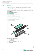
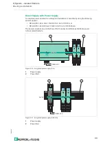
A complete power solution for a K-System installation is possible by using the following 

power supplies:

KFA6-STR-1.24.4 from 115/230 V AC to 24 V DC/4 A or

KFA6-STR-1.24.500 from 115/230 V AC to 24 V DC/500 mA

The power supplies snap on the Power Rail to easily and efficiently distribute power 

to the isolated barriers.

Figure 3.10 Integrated power supply (4 A)

Figure 3.11 Integrated power supply (500 mA)

1

Power supply

2

Power Rail

1

Power supply

2

Power Rail

1

3

4

6

2

5

1

3

4

6

2

5

13

12

9

10

7

14 15

11

8

13

12

9

10

7

14 15

11

8

2

1

115/230 V AC

24 V DC

1

3

4

6

2

5

1

3

4

6

2

5

13

12

9

10

7

14 15

11

8

13

12

9

10

7

14 15

11

8

PWR

1

3

4

6

2

5

13

15

12

9

10

7

14

11

8

1

115/230 V AC

2

24 V DC

Summary of Contents for K-System

Page 1: ...ISO9001 K System Isolated Barriers Manual...

Page 2: ...ion as well as the supplementary clause Expanded reservation of proprietorship Worldwide Pepperl Fuchs Group Lilienthalstr 200 68307 Mannheim Germany Phone 49 621 776 0 E mail info de pepperl fuchs co...

Page 3: ...the Isolators 16 2 6 Operating Elements 17 2 7 Label Carrier 19 2 8 DIN Mounting Rail 19 2 9 Power Rail 20 3 Mounting and Installation 21 3 1 Mounting 21 3 2 Connection 26 4 Configuration 35 5 Operati...

Page 4: ...K System Isolated Barriers Contents 4 2020 12...

Page 5: ...intenance and repair Troubleshooting Dismounting Disposal The documentation consists of the following parts Present document Instruction manual Datasheet Additionally the following parts may belong to...

Page 6: ...find warning messages whenever dangers may arise from your actions It is mandatory that you observe these warning messages for your personal safety and in order to avoid property damage Depending on...

Page 7: ...riers have a galvanic isolation between the field circuit and the controller Figure 2 1 Function isolating amplifying and transforming signals The K System consists of wide range of isolated barriers...

Page 8: ...width KF devices or KH devices with 40 mm width The 3 housing widths versions have the same system characteristics All devices can be mounted on the 35 mm DIN mounting rail or the Power Rail See chapt...

Page 9: ...Digital devices monitor speed direction of rotation slip flow rates and time Analog devices monitor transmitter signals temperature signals and load cells Configured using keypad or PACTwareTM softwar...

Page 10: ...20 12 10 K System Isolated Barriers Product Specifications KH Device Housing Figure 2 6 KH device housing 40 mm 10 11 12 16 17 18 4 5 6 22 23 24 7 8 9 13 14 15 1 2 3 19 20 21 1 CHK PWR OUT KHA6 SH Ex1...

Page 11: ...erminals or spring terminals The order designation of the versions of the KC devices with spring terminals has the extension SP As an alternative to the factory equipped terminal blocks the devices ca...

Page 12: ...oltages higher than 50 V AC The insulation of the removable terminal blocks provides protection against direct contact The insulation corresponds to a basic insulation according to EN 61010 1 for a ra...

Page 13: ...rminal Designation Figure 2 9 KC device housing 12 5 mm Figure 2 10 KF device housing 20 mm Note See corresponding datasheets for precise terminal designation 9 10 8 6 7 5 2 4 1 3 3 4 1 2 7 8 5 6 9 10...

Page 14: ...ions Figure 2 11 KF device housing 40 mm Figure 2 12 KH device housing 40 mm 19 21 15 9 13 7 20 14 8 22 24 18 12 16 10 23 17 11 1 3 2 4 6 5 1 2 3 7 8 9 131415 192021 4 5 6 101112 161718 222324 10 11 1...

Page 15: ...C DC wide range supply of 20 V DC to 90 V DC or 48 V AC to 253 V AC Blue 4 indicates devices that process signals from the hazardous area Figure 2 13 Color identification of devices 1 green 2 black 3...

Page 16: ...ation of fault required No fault Off No malfunction device is operating properly Yellow LED Switching states of binary inputs and outputs On Possible causes of the output The relay is energized The NO...

Page 17: ...ion These operating elements are DIP switches Via DIP switches you can configure the basic functions of the device Figure 2 15 Rotary switches Via rotary switches you can configure the basic functions...

Page 18: ...C with parameterization software PACTwareTM Via parameterization software PACTwareTM you can configure the device easily The configuration data can be edited and saved The parameterization software he...

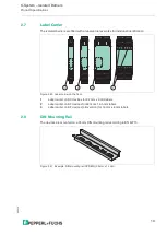
Page 19: ...re 2 20 Label carrier on the front 2 8 DIN Mounting Rail The devices are mounted on a 35 mm DIN mounting rail according to EN 60715 Figure 2 21 Example DIN mounting rail UPR MR 35 mm x 15 mm 1 Label c...

Page 20: ...Rail is protected from contamination Additionally the cover and end caps prevent that electrically conductive parts come in contact with the Power Rail Power Rail is available in two versions Power Ra...

Page 21: ...Danger Explosion hazard from pollution An excessively polluted surface of the device can become conductive and consequently ignite a surrounding potentially explosive atmosphere Ensure that you insta...

Page 22: ...safe circuits in a potentially explosive atmosphere sparks can ignite the surrounding atmosphere Only connect or disconnect energized non intrinsically safe circuits in the absence of a potentially e...

Page 23: ...g direction and without restriction Figure 3 2 Vertical mounting without separation distance group mounting Figure 3 3 Horizontal mounting without separation distance group mounting 1 3 4 6 2 5 1 3 4...

Page 24: ...um separation distance See following figures KC devices with 12 7 mm housing width housing type A min 6 mm KF devices with 20 mm housing width housing type B min 10 mm KF devices with 40 mm housing wi...

Page 25: ...ing of KF devices with 20 mm housing width single device mounting Figure 3 6 Horizontal mounting of KF devices with 40 mm housing width single device mounting 13 12 9 10 7 14 15 11 8 13 12 9 10 7 14 1...

Page 26: ...urrounding atmosphere Only connect or disconnect energized non intrinsically safe circuits in the absence of a potentially explosive atmosphere Danger Danger to life from electric shock Absent or insu...

Page 27: ...xplosion hazard from wrong separation distances If you do not observe the minimum separation distance between 2 intrinsically safe circuits this can lead to added currents or voltages This can result...

Page 28: ...inst reconnection 3 Verify that the device is de energized at all poles 4 Provide protection from adjacent live parts if present Warning Risk of short circuit Live working can cause injuries to the op...

Page 29: ...es create complicated and expensive wiring systems After all isolated barriers are connected there is a significant amount of wiring and more wiring must be added for extra functions such as line faul...

Page 30: ...rotected It prevents damage caused by reverse supply voltage or by installing too many isolators The isolators on the Power Rail feature integrated device fuses Any faults in the isolator or in the si...

Page 31: ...Danger to life from electric shock Absent or insufficient insulation can result in electric shock Only connect supplies that provide protection against electric shock to power feed modules e g SELV or...

Page 32: ...the fuse in a power feed module fails the redundant supply continues to energize the isolators through their Power Rail connection Figure 3 9 Redundant power connections 1 Replaceable fuse 2 Power fee...

Page 33: ...24 V DC 500 mA The power supplies snap on the Power Rail to easily and efficiently distribute power to the isolated barriers Figure 3 10 Integrated power supply 4 A Figure 3 11 Integrated power suppl...

Page 34: ...or pulling the adapter Plugging or pulling the adapter in a potentially explosive atmosphere can cause sparks that can ignite the surrounding atmosphere Only plug or pull the adapter in the absence of...

Page 35: ...that can ignite the surrounding atmosphere Only use operating elements e g switch slider button etc in the absence of a potentially explosive atmosphere Caution Potential device malfunction from chan...

Page 36: ...s Device faults The isolators are designed so that internal faults are detected and reported In the case of a power failure the outputs are switched to the de energized state Danger Explosion hazard f...

Page 37: ...has a fault indication output FAULT The fault indication output is active in a normal state and inactive in a fault state closed circuit principle Is it impossible to reverse the detection direction o...

Page 38: ...e signal and transmits the fault message signal to the controller by means of a potential free contact The potential free contact simultaneously reports the device power failure or the failure of one...

Page 39: ...standard signal common to all manufacturers Sensor signals are converted into standard signals via signal converters For more diagnostic options the NAMUR organization published NAMUR recommendation...

Page 40: ...ed non intrinsically safe circuits in the absence of a potentially explosive atmosphere Danger Danger to life from using damaged or repaired devices Using a defective or repaired device can compromise...

Page 41: ...ewdriver 4 into the groove of the red mounting slider 3 2 Turn the screwdriver 4 in the groove until the red mounting slider 3 springs back 3 Repeat these steps on the other side of the device 4 Remov...

Page 42: ...compatible Pt100 2 3 4 wire technology Resistor 0 to 400 with freely definable characteristic Potentiometer Thermocouples of all types internal cold junction external reference Current output HART com...

Page 43: ...ptions see data sheets extended ambient temperature range up to 70 C 158 F necessary mounting conditions see chapter 3 1 Storage Temperature 40 C to 90 C 40 F to 194 F exceptions see data sheets Refer...

Page 44: ...5 mm2 14 AWG Observe the tightening torque of the terminal screws The tightening torque is 0 5 Nm to 0 6 Nm Fire Protection Class Housing V2 according to UL 94 standard Unless stated otherwise all de...

Page 45: ...terminal blocks 20 mm or 40 mm width H Version without removable terminal blocks 20 mm or 40 mm width Position 3 D DC power supply A AC power supply U AC DC power supply Position 4 0 without power sup...

Page 46: ...SON Switch amplifier with NAMUR output SOT Switch amplifier with passive potential free transistor output SR Switch amplifier with relay output SRA Switch amplifier with relay output 2 1 operation mo...

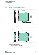
Page 47: ...ice is 124 mm 4 9 in in height When using spring terminals the device is 131 mm 5 16 in in height Figure 7 2 Number of terminal blocks maximum 4 Dimension drawing with screw terminals When using screw...

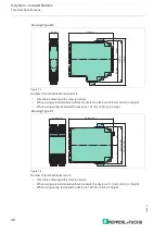
Page 48: ...in height When using spring terminals the device is 131 mm 5 16 in in height Figure 7 4 Number of terminal blocks max 8 Dimension drawing with screw terminals When using screw terminals with test sock...

Page 49: ...device is 131 mm 5 16 inch in height Figure 7 6 Number of terminal blocks max 15 Dimension drawing with screw terminals When using screw terminals with test sockets the device is 124 mm 4 9 in in heig...

Page 50: ...tem Isolated Barriers Technical Specifications Figure 7 7 Figure 7 8 Housing Type E Housing Power Supply 4 A 115 mm 4 5 93 mm 3 66 40 mm 1 6 140 mm 5 51 88 mm 3 46 99 mm 3 9 103 5 mm 4 07 PE L1 N Prim...

Page 51: ...K System Isolated Barriers Notes 2020 12 51...

Page 52: ...Pepperl Fuchs Quality Download our latest policy here www pepperl fuchs com quality www pepperl fuchs com Pepperl Fuchs Subject to modifications Printed in Germany DOCT 0187U...

Reviews: