K-System – Isolated Barriers
Operation
20
20
-1
2
37
5.2
Fault Output
Depending on the configuration of the devices, these faults are transmitted to the outputs
at the control side and in separate fault indication outputs as additional information.
•
Red fault indication LEDs on the isolator
•
Fault indication output
•
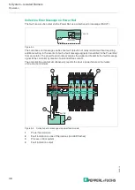
Collective error message on Power Rail
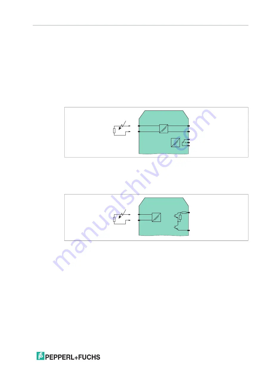
Fault Indication Output
Line and device faults are transmitted if the device has a fault indication output (FAULT).
The fault indication output is active in a normal state and inactive in a fault state (closed-circuit
principle). Is it impossible to reverse the detection direction of the fault indication output.
Figure 5.1
Line Fault Transparency (LFT)
Line fault transparency makes electrical conditions on the field side visible on the control side
of the isolator. This enables line faults between the isolator and the field device to be detected
and transmitted to the control system via the signal line.
Figure 5.2 Example of line fault transparency with digital input
2-
1+
7
8 (+/-)
FAULT
10
11
12
2+
1+
7+
9-
FAULT

