- 10 -
IM-ENG-114/GB
E) from one to six Power Modules which must be all of the same version; based on the type of system there are
two possibilities:
1550/PM-230 is the module that implements conversion for coupling with system type-230.
1550/PM-115 is the module that implements conversion for coupling with system type-115.
5.1 GENERALITIES
The PS1550 is a continuous voltage power system providing 24V and maximum 1kW power. It has been construc-
ted modularly and operates in switching mode to maximize conversion efficiency.
Two separate power lines, 230 Vac or 115 Vac, have been foreseen in addition to a 130 Vdc line. They are redun-
dant, therefore failure of one of the two has no effect on output which remains unaltered.
5. FUNCTIONAL DESCRIPTION
~ ~
~ ~
~ ~
LINE 1 ON
Alarm
contact
# 1
~
~
~
~
LINE FILTERS
Module with
input terminals
and alarm
LINE 2 ON
Alarm
Alarm
Output
Failure
Line Voltage Bus
Output BUS
Power Module
# 1
Line Module # 1
Line Module # 2
(redundant)
Alarm
contact
# 2
Power Line
1 AC/DC
+
24 V
DC
Output
TERMINATION
OUTPUT
MODULE
1
16
1
16
(# 3 / # 4)
+24 V
0 V
Fan failure detector
Fan 1
OK
Fan 2
OK
Fan 3
OK
OUT ON
OVERLOAD
VOLTAGE
CURRENT
Safety Block
Switch
Power Line
2 AC/DC
Power Module
# 2
Power Module
# 5
Power Module
# 6
OUT ON
OVERLOAD
VOLTAGE
CURRENT
OUT ON
OVERLOAD
VOLTAGE
CURRENT
(*) I M P O R T A N T !
WHEN TWO POWER LINES ARE UTILIZED, LINE 1 MUST BE ISOLATED FROM LINE 2 (NO COMMON POINTS)
OTHERWISE A POWER ISOLATION TRANSFORMER IS NECESSARY ON ONE OF THE TWO LINES.
*
( )
*
( )
*
( )
*
( )
TRIMMER for regulating
output voltage of PM
modules (24.7 Vdc
±
10%)
*
( )
OUT ON
OVERLOAD
VOLTAGE
CURRENT
ISOLA
TED FROM EACH OTHER
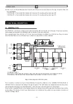
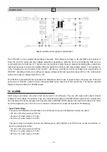
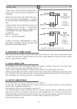
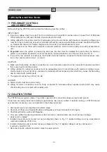
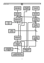
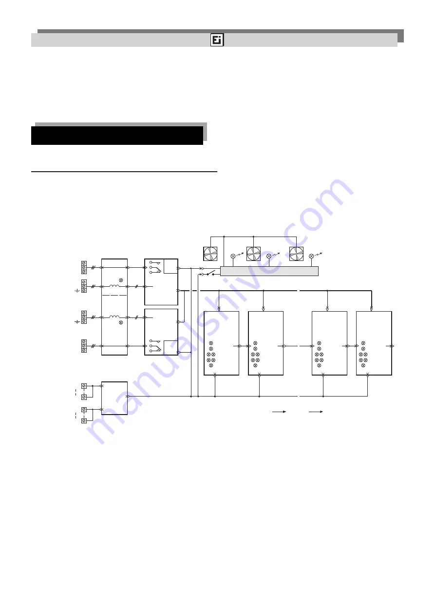
Fig. 3.
Block diagram of PS1550 system.
The conversion is carried out by six Power Modules through the utilization of six LAMBDA PH150S-280-24 or
PH150S-110-24 components according to the type of system. The six Modules are independent and can be extrac-
ted and inserted (hot plug-in insertion/extraction) in the rack even when the system is under tension.
They function in parallel thanks to the implementation of a sharing circuit which guarantees that they all work at the
same voltage. The failure of one Power Module does not compromise the system but only implies a reduction of
maximum voltage output.


