- 19 -
7.1 PRELIMINARY CONTROLS
AND CONNECTIONS
Before starting the PS1550 power system the following must be verified:
INPUT LINES
A. Input line voltage must be correct and in accordance with specified nominal value on panel front of Modules
1550/TB-IN (first on left) and 1550/LM (third and fourth from left).
B. Wiring utilized for input lines must be of adequate sizing (in accordance with maximum requested voltage) and
must be firmly connected to respective terminals without any exposed parts that may cause shortcircuiting (Pha-
se, Neutral and Ground or Positive, Negative and Ground) or potential hazards for user .
C. Power lines must be fitted with automatic protection switches which remain readily and easily accessible to
user.
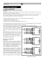
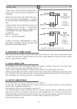
D. Important: when the system is powered by two lines, the lines must be isolated from each other (no common
points) or an isolation transformer must be inserted in series suitable for one of the two lines (see fig. 9).
E. If one of the two currents is continuous, the Positive terminal must be connected to the first terminal above, rela-
tive to the chosen section (Line 1 or Line 2).
OUTPUTS
A. Make sure that polarity of output connections is correct (positive output must be connected to positive load and
this is also true for all other loads).
B. Wiring utilized for output connections must be adequately sized (in accordance with maximum voltage reque-
sted by load) and must be firmly connected to terminals without exposed parts which may cause shortcircuiting
due to contact with metallic parts.
C. The system must be free of short circuits.
ALARMS
A. Alarm circuits must be wired correctly.
B. Wiring for alarm connections must be firmly connected to terminals without exposed parts which may cause
shortcircuiting due to contact with metallic parts.
7.2 ISOLATION TESTING
The PS1550 power system utilizes Y type filter capacitors for connections between inputs and ground.
It has been accurately tested and isolation specifications have been verified. If isolation testing on PS1550 should
ever become necessary, carry out operation in the following manner:
1. Disconnect input and output lines and alarm relays.
2. Shortcircuit Phase and Neutral (Positive and Negative) at input terminal for both inputs.
3. Shortcircuit Positive output with Negative.
4. Only use certified measuring instruments which furnish a controlled ramp rise (must be free of voltage
steps) and no “spikes”.
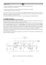
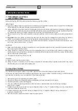
5. Isolation Input-Ground is carried out as per diagram shown in Fig. 11: applied voltage must be sinusoidal at
maximum amplitude 2500 Vrms.
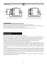
6. Isolation Output-Ground is carried out as per diagram in Fig. 12: applied voltage must be continuous at
maximum value 500 Vdc.
7. Reconnect inputs, outputs and alarm relays to power system.
IM-ENG-114/GB
7. OPERATING INSTRUCTIONS

