background image

 2

01

7-

11

30

PXV...-F200-SSI-V19

Appendix

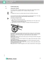
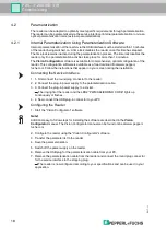
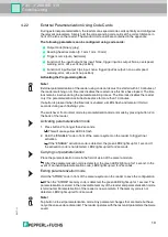
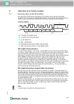
6.1.5

Code Cards for Adjusting Input/Output 3

Parameterization enables you to assign various functions to input/output 3 on the read head. 

The following input/output functions are available:

Input: none

Output: Overspeed

Output: Warning

Output: Fault

Output: Event

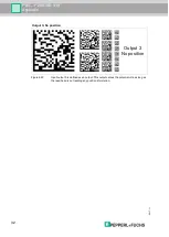
Output: No position

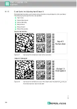
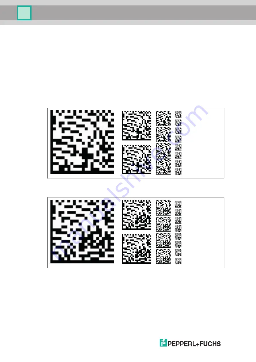
Figure 6.17

Input/output 3 is defined as an input but has no function.

Figure 6.18

Input/output 3 is defined as an output. This output carries the potU

B

 as long as 

the defined maximum speed is exceeded.

Input 3: No Function

Output 3: Overspeed

Input 3

No function

Output 3

Overspeed

Summary of Contents for PXV***-F200-SSI-V19 Series

Page 1: ...PXV F200 SSI V19 DataMatrix Positioning System FACTORY AUTOMATION MANUAL ...

Page 2: ...rms of Delivery for Products and Services of the Electrical Indus try published by the Central Association of the Electrical Industry Zentralverband Elektrotechnik und Elektroindustrie ZVEI e V in its most recent version as well as the supplementary clause Expanded reservation of proprietorship PXV F200 SSI V19 ...

Page 3: ... Commissioning 17 4 1 Aligning the Reader 17 4 2 Parameterization 17 4 2 1 Internal Parameterization Using Parameterization Software 17 4 2 2 External Parameterization Using Code Cards 18 5 Operation and Communication 20 5 1 Communication via the SSI Interface 20 6 Appendix 22 6 1 Code Cards for External Parameterization 22 6 1 1 Code Cards with Special Functions 22 6 1 2 Code Cards for Adjusting ...

Page 4: ... applicable EU type examination certificate EU declaration of conformity Attestation of conformity Certificates Control drawings Instruction manual Other documents 1 2 Target Group Personnel Responsibility for planning assembly commissioning operation maintenance and dismounting lies with the plant operator Only appropriately trained and qualified personnel may carry out mounting installation comm...

Page 5: ...ayed in descending order as follows Informative Symbols Action This symbol indicates a paragraph with instructions You are prompted to perform an action or a sequence of actions Danger This symbol indicates an imminent danger Non observance will result in personal injury or death Warning This symbol indicates a possible fault or danger Non observance may cause personal injury or serious property d...

Page 6: ...fficient reserves for extensions or systems with several branches and parallel conveyor routes The extensive yet user friendly parameterization options as well as the freely configurable inputs and outputs mean that the reader can easily be adapted to suit each application Figure 2 1 Schematic diagram of the alignment of the code tape and reader 2 2 USB Interface The Vision Configurator is a usefu...

Page 7: ...der responds synchronously with the 25 bit comprehensive response telegram You can define the structure and content of the response telegram using the Vision Configurator configuration software This may include position data in an X and Y direction as well as speed and diagnostic data During live operation the reader is connected for communication via the SSI interface using the Main connector 2 4...

Page 8: ...es green Off Off Flashes Off Off Alignment Z setpoint value fflash 2 Hz Off Flashes red Off Off Off Off Off Alignment Code tape outside read range fflash 2 Hz Off Lights up red Off Off Off Off Off System error Off Lights up green Flashes x x Off Off Normal operation SSI communication active fflash 2 Hz LEDs marked with x indicate the status of the relevant output Off Flashes red Flashes x x Off Of...

Page 9: ...Off Green 1 sec Flashes Off Off Off Off Code card detected fflash 2 Hz x Off x x x Off Off Time lock for buttons disabled Flashes Green Off Off Off Off Off Position query via USB interface code within the read range Flashes Flashes red Off Off Off Off Off Position query via USB interface no code within read range x x x x x Lights up Lights up Internal error Return to Pepperl Fuchs LED 1 COM 2 PWR ...

Page 10: ...y deposits and dust 2 Ensure that the surface is dry clean and stable 3 Pull away a few centimeters of the protective film at the beginning of the code tape Place the code tape at the precise point of the required starting position on the surface and press to attach 4 Then affix the code tape along the desired traverse distance Remove the protective film gradually so that the code tape does not ac...

Page 11: ...ode Tape and Reader Order Designation Description PXV00001 CA25 Code tape 1 track length 1 m PXV100000 CA25 Code tape 1 track length 100 000 m 000 009 0 m PXV AA25 www pepperl fuchs com Y Z X Note Expansion Joints and Code Tapes If the system covers longer distances expansion joints are integrated in the system structure We recommend creating breaks along the code tape The resulting gap must not e...

Page 12: ...at the guidance of the moving system component is such that the reader depth of focus range is not exited during operation 1 Secure the reader to the moving component of your system via the four screws on the reader mounting adapter 2 Mount the reader vertically so that the lens with ring light and camera module are aligned toward the code tape Figure 3 2 Vertical alignment tolerance 3 Alternative...

Page 13: ...ance from the reader to the code tape is the same as the read distance of the reader Optimal Read Distance Z Axis 1 Read Distance Model number Read distance mm Depth of focus mm PXV100 100 50 Reader Dimensions 30 30 1 7 1 2 3 4 5 6 8 7 1 2 3 4 5 6 8 70 80 38 5 70 14 5 1 2 22 51 ø 25 12 M12 x 1 9 4 x M6 40 ...

Page 14: ...Figure 3 5 Connector assignment Color Assignment Single ended female cordsets by Pepperl Fuchs are manufactured in accordance with EN60947 5 2 When using a type V19 single ended female cordset with an open cable end the following color assignment applies Caution When selecting the length of the mounting screws ensure that the maximum insertion depth of the screws in the threaded inserts on the rea...

Page 15: ...d The following points relating to shielding must also be noted Use metal cable clips that cover large areas of the shield After installing the cable shield in the control cabinet place it directly on the equipotential bonding rail Direct the protective grounding connections to a common point in a star configuration The cross section of the cables used for grounding should be as large as possible ...

Page 16: ... the device or cause the device to malfunction Electrical connections with reversed polarity can damage the device or cause the device to malfunction Connect the device to direct current DC Ensure that the supply voltage rating is within the specified device range Ensure that the connecting wires on the female cordset are connected correctly ...

Page 17: ...ode tape is too small the yellow LED5 lights up If the distance between the camera and the code tape is too large the yellow LED5 goes out Within the target range the yellow LED5 and the green LED2 flash synchronously Set the distance between the reader and the code tape so that the yellow LED5 and the green LED2 flash synchronously Y coordinate If the optical axis of the reader is too low relativ...

Page 18: ...ons that appear on your screen during the installation Connecting the Service Interface 1 1 First connect the round plug connector to the reader 2 2 Connect the plug in power supply to the parameterization cable 3 3 Connect the plug in power supply to a socket The ring light of the reader and the LED2 PWR ADJ ERR NO CODE lights up continuously or flashes 4 4 Now connect the USB plug in connector t...

Page 19: ...not detected LED2 lights up red for 2 seconds Carrying out parameterization Place the parameterization code in the field of vision of the camera module After the parameterization code is detected the green LED2 lights up for 1 second In the event of an invalid parameterization code LED2 lights up red for 2 seconds Exiting parameterization mode Hold the STORE code in front of the camera system on t...

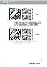
Page 20: ... operates with the last valid parameters that were saved USE For test purposes the reading head operates with the parameters that have just been modified The parameterization is not saved however After being switched off and on again the reading head operates with the last valid parameters that were saved DEFAULT All parameters in the reading head are overwritten with the original default settings...

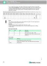
Page 21: ...D0 LSB has been transferred the data cable switches to low until the monoflop time Tm has elapsed A further data transfer can only be initiated when the data cable switches to high again or the pulse interval time Tp has elapsed At the end of the pulse sequence the last falling pulse edge triggers the monoflop time Tm The monoflop time Tm determines the lowest transfer frequency SSI output format ...

Page 22: ...7 6 5 4 3 2 1 Data XP21 XP20 XP19 XP18 XP17 XP16 XP15 XP14 XP13 XP12 XP11 XP10 XP9 XP8 XP7 XP6 XP5 XP4 XP3 XP2 XP1 XP0 Out Wrn Err MSB LSB Status bits Note The number of position bits required in the X direction depends on the track length of your system and the required position resolution Example max track length 300 m required position resolution 1 mm 19 bits are enough to display the X positio...

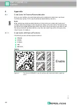
Page 23: ...ctions ENABLE STORE CANCEL USE DEFAULT Figure 6 1 The code card ENABLE is used to activate external parameterization operating mode Note When performing external parameterization with code cards we recommend copying and printing out the relevant pages in this manual and cutting out the code cards This prevents the read head from mistakenly detecting another code card on the same page If you intend...

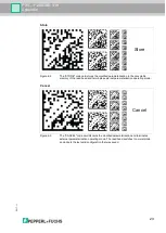
Page 24: ...memory of the read head and terminates external parameterization operating mode Figure 6 3 The CANCEL code card discards the modified parameterization and terminates external parameterization operating mode The read head switches to normal mode and adopts the last valid configuration that was saved Store Cancel Store Cancel ...

Page 25: ...head then operates with this configuration However if the read head is switched off and on again the configuration is lost and the read head operates with the last valid configuration that was saved This function is used primarily for test purposes Figure 6 5 The DEFAULT code card restores the settings of the read head to default and terminates external parameterization operating mode Use Default ...

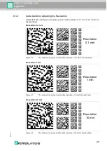
Page 26: ... the read head Figure 6 6 The code card assigns a position data resolution of 0 1 mm to the read head Figure 6 7 The code card assigns a position data resolution of 1 mm to the read head Figure 6 8 The code card assigns a position data resolution of 10 mm to the read head Resolution 0 1 mm Resolution 1 mm Resolution 10 mm Resolution 0 1 mm Resolution 1 mm Resolution 10 mm ...

Page 27: ...2017 11 26 PXV F200 SSI V19 Appendix Maximum Length of the Code Tape Resolution of the read head mm Maximum length of the code tape km 10 10 1 10 0 1 10 ...

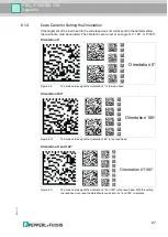
Page 28: ...at an angle of 0 180 or 0 180 Figure 6 9 The code card assigns the orientation 0 to the read head Figure 6 10 The code card assigns the orientation 180 to the read head Figure 6 11 The code card assigns the orientation 0 and 180 to the read head With this setting the read head can read the Data Matrix code band in 0 and 180 orientation Orientation 0 Orientation 180 Orientation 0 and 180 Orientatio...

Page 29: ...ce The following transfer rates are available 38400 bit s 57600 bit s 76800 bit s 115200 bit s 230400 bit s Figure 6 12 The transfer rate of the read head for communication via the interface is preset to 38400 bit s Figure 6 13 The transfer rate of the read head for communication via the interface is preset to 57600 bit s Transfer rate 38400 bit s Transfer rate 57600 bit s 38400 Bit s 57600 Bit s ...

Page 30: ...bit s Figure 6 15 The transfer rate of the read head for communication via the interface is preset to 115200 bit s Figure 6 16 The transfer rate of the read head for communication via the interface is preset to 230400 bit s Transfer rate 76800 bit s Transfer rate 115200 bit s Transfer rate 230400 bit s 76800 Bit s 115200 Bit s 230400 Bit s ...

Page 31: ...put functions are available Input none Output Overspeed Output Warning Output Fault Output Event Output No position Figure 6 17 Input output 3 is defined as an input but has no function Figure 6 18 Input output 3 is defined as an output This output carries the potential UB as long as the defined maximum speed is exceeded Input 3 No Function Output 3 Overspeed Input 3 No function Output 3 Overspeed...

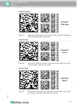
Page 32: ...6 20 Input output 3 is defined as an output This output carries the potential UB as long as an error message is present on the read head Figure 6 21 Input output 3 is defined as an output This output carries the potential UB as long as an event marker is present in the read field of the read head Output 3 Warning Output 3 Fault Output 3 Event Output 3 Warning Output 3 Error Output 3 Event ...

Page 33: ...F200 SSI V19 Appendix Figure 6 22 Input output 3 is defined as an output This output carries the potential UB as long as the read head is not reading any position information Output 3 No position Output 3 No position ...

Page 34: ...uchs GmbH 68307 Mannheim Germany Tel 49 621 776 0 E mail info de pepperl fuchs com USA Headquarters Pepperl Fuchs Inc Twinsburg Ohio 44087 USA Tel 1 330 4253555 E mail sales us pepperl fuchs com Asia Pacific Headquarters Pepperl Fuchs Pte Ltd Company Registration No 199003130E Singapore 139942 Tel 65 67799091 E mail sales sg pepperl fuchs com DOCT 5880 11 2017 ...

Reviews: