SLCT* and SLCT*/35 safety light curtains
Installation
2
7
1
6
9
5
2
0
1
7
-1
2
23
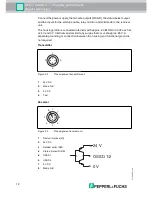
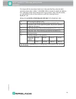
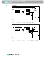
The function can be activated or deactivated at the 8 pin connector of the receiver
SLCT.
The two feedback contacts on the external switching elements must be placed
between 24 VDC and the relay monitor input in order to activate the relay monitor.
The relay monitor function is deactivated if the relay monitor input is bridged with
the status/select output.
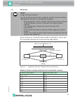
A/B mode operating mode
Operating mode A or operating mode B must be configured both on the
transmitter unit and on the receiver unit. The modes are used to prevent cross-talk
from adjacent SLCT safety light curtains.
4.4.1
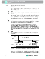
Signal outputs on the receiver unit
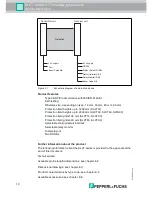
Status/Select RI-RM output
The output indicates the same states as the restart/status indicator.
This signal output indicates operational readiness and is active when the
protection field is free and startup enable can be activated in order to switch on
the OSSD. Internal or external faults and a dirty lens, are also signaled at this
output.
If an external fault occurs, the output switches on and off at a frequency of 1 Hz.
The following faults may be the cause:
■
Relay monitor faulty
■
Low supply voltage
■
Short or crossed circuits at the OSSD outputs and
■
Level change at the mode input during operation
Internal faults cause the output to switch on and off at a frequency of 5 Hz.
If the safety light curtain is not adjusted correctly or the front lenses are not clean,
the output switches on and off at a frequency of 2.5 Hz.
The output is also used to define the preset operating mode during startup.
Bypassing this output to the restart and/or relay monitor inputs deactivates the
relevant operating mode.
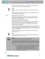
OSSDs
The receiver has two safe outputs, which are short circuit and cross circuit proof.
The OSSDs switch off as soon as a light beam is interrupted. Switching times, .
Note!
An open relay monitor input results in a fault. The yellow indicator LED flashes at a
frequency of 1 Hz in case of a fault.


