2
7
1
6
9
5
2
0
1
7
-1
2
26
SLCT* and SLCT*/35 safety light curtains
Installation
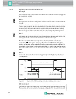
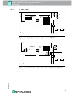
Relay monitor input
Auxiliary contacts on switching elements connected downstream of the OSSDs
can be connected to the relay monitor input. This allows these elements to be
monitored. Use NC contacts (see chapter 4.4.4). All monitored switching
elements must be connected in series. One end of this series connection must be
connected to the positive power supply and the other end to the relay monitor
input.
The feedback contacts on the external switching elements must guarantee a
reliable contact at a voltage of 20 VDC and a current of 5 mA.
If the external switching element is not activated within 200 ms, this is identified as
a fault and safe mode is activated.
To disable the function, the input must be bridged with the status/select output. An
open input also activates the relay monitor function.
A/B mode input
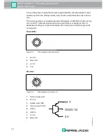
If the input is open or connected to 0 V, the safety light curtain operates in mode A.
The inputs must be connected to the supply voltage 24 VDC to switch to mode B.
After the supply voltage is switched on, the transmitter or receiver selects mode A
or mode B, depending on the applied voltage. Make sure that the transmitter and
receiver are operating in the same mode.
If the level at the input changes during operation, this is identified as a fault and
the system switches to safe mode.
Danger!
Danger to life due to electric shock
Insufficient separation distances can negate the safe separation of a SELV/PELV
supply of the protective equipment. This can lead to a particularly high voltage on
the device and present a danger to life.
The protection class III of the protective equipment and the necessary safe
separation distance must be taken into account when designing the insulation
coordination of the electrical installation or machine.
For more information, also see IEC 60204, IEC 60664 and IEC 61140 and the
relevant national regulations.

