2
0
2
0
-0
3
18
Commissioning
4.3
Connection to the Network
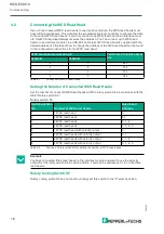
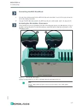
The connection to EtherNet/IP is made via the two RJ45 EtherNet/IP P1 and P2 sockets on the
underside of the interface module. The front socket is labeled P1 and the rear socket is labeled
P2. Connect the device to the EtherNet/IP network at the interface with the label "P1" (cable
from master) or "P2" (further cable to the next slave).
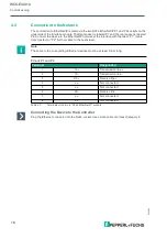
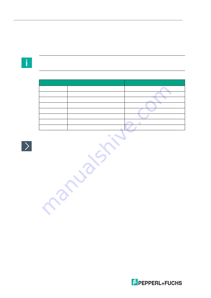
Pinout P1 and P2
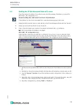
Connecting the Device to the Controller
Plug the Ethernet connector into the RJ45 socket. Use a data cable of at least Category 5.
Note
The cable to the surrounding Ethernet devices must be at least 0.6 m long.
Terminal
Designation
1
TD+
Transmission line +
2
TD-
Transmission line -
3
RD+
Receive line +
4
n.c.
Not connected
5
n.c.
Not connected
6
RD-
Receive line -
7
n.c.
Not connected
8
n.c.
Not connected
Table 4.3
Terminals of the 8-pin "RJ45 EtherNet/IP" sockets

