Commissioning
2
0
2
0
-0
3
21
4.5
Network Settings
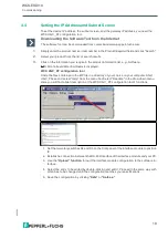
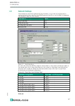
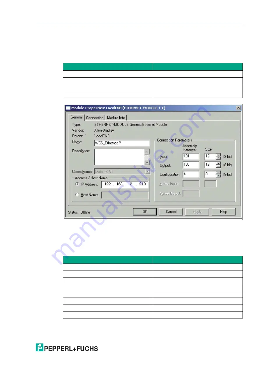
The interface modul uses implicit messaging. Therefore, any position and speed data is
mapped directly in the controller. The following figure shows the correct setting for integrating
the interface module into the network.
Figure 4.2
Network settings
You can enter all values with the exception of the values for "Input Size" and "Output Size" on
the input screen of your project planning tool. The values for "Input Size" and "Output Size"
depend on the number of readers and the desired data output. You have to adjust these
according to your hardware configuration.
Values for "Input Size" and "Output Size"
Example:
Parameters
Value
Input assembly
101
Output assembly
100
Configuration assembly
4
Minimum RPI
20 ms
Hardware configuration
"Input Size" and "Output Size"
1 reader
4 bytes
2 readers
8 bytes
3 readers
12 bytes
4 readers
16 bytes
1 reader with velocity output
6 bytes
2 readers with velocity output
12 bytes
3 readers with velocity output
18 bytes
4 readers with velocity output
24 bytes

