Communication with WCS read heads
2
0
2
0
-0
3
21
5
Communication with WCS read heads
5.1
Request Byte for Read Heads
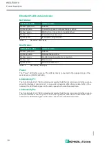
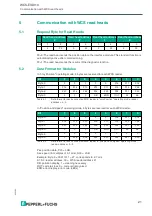
F0=0: The read head sends the position data to the interface module. This standard function is
automatically active after commissioning.
F0=1: The read head sends the results of the diagnostic function.
5.2
Data Format for Modules
In "only Position" operating mode, 4 bytes are reserved for each WCS reader.
In "Position and Speed" operating mode, 6 bytes are reserved for each WCS reader.
Pxx: position data, P00 = LSB
Sxx: speed (in multiples of 0.1 m/s), S00 = LSB
Example: Byte 5 = 00011011 = 27, corresponds to 2.7 m/s
A1, A0: reader address, 00 = WCS reader address #1
DB: pollution display, 1 = cleaning necessary
OUT: code rail loss, 0 = code rail recognized
ERR: error display, error code (LEDs)
Read head address
3
Read head address
2
Read head address
1
Read head address
0
Bit
7
6
5
4
3
2
1
0
0
F0
0
F0
0
F0
0
F0
Bit
7
6
5
4
3
2
1
0
Byte 0
0
0
0
0
0
P18
P17
P16
Byte 1
P15
P14
P13
P12
P11
P10
P09
P08
Byte 2
P07
P06
P05
P04
P03
P02
P01
P00
Byte 3
0
0
0
DB
ERR
OUT
A1
A0
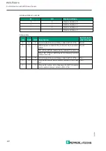
Table 5.1
Data format for each connected WCS reader in "only Position" operating mode, reader
address = 0...3
Bit
7
6
5
4
3
2
1
0
Byte 0
0
0
0
0
0
P18
P17
P16
Byte 1
P15
P14
P13
P12
P11
P10
P09
P08
Byte 2
P07
P06
P05
P04
P03
P02
P01
P00
Byte 3
0
0
0
DB
ERR
OUT
A1
A0
Byte 4
0
0
0
0
0
0
0
0
Byte 5
0
S06
S05
S04
S03
S02
S01
S00
Table 5.2
Data format for each connected WCS reader in "Position and Speed" operating mode,
reader address = 0...3

