Installation
2
0
2
0
-0
3
11
3
Installation
3.1
Mounting
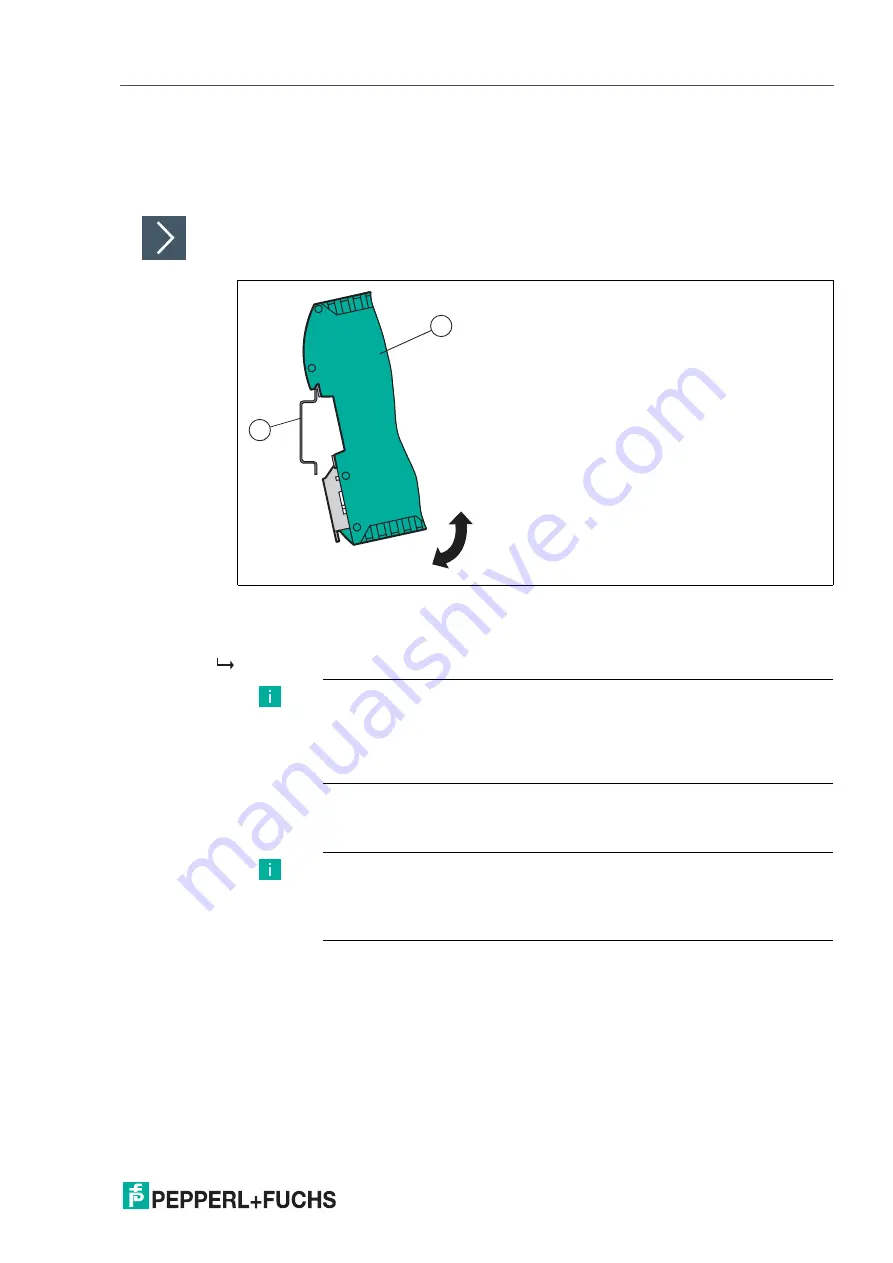
Mounting the Modules
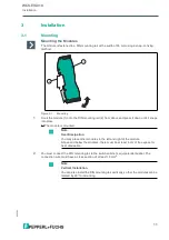
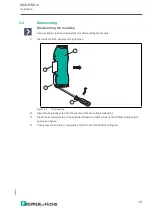
The module is fastened to a DIN mounting rail with a width of 35 mm using a snap-on fixing
method.
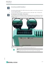
Figure 3.1
Mounting
1.
Hook the module (1) onto the DIN mounting rail (2) from above and press it down until it snaps
into place.
The module is mounted.
2.
You must connect the DIN mounting rail to the switch cabinet's equipotential busbar. The
connection wire must have a cross section of at least 10 mm
2
.
2
1
Note
Heat Dissipation
You may place other modules to the left and right of the module.
Above and below the modules, there must be at least 5 cm of free space for
heat dissipation.
Note
Vertical Installation
You can also install the DIN mounting rail vertically, so that the modules can be
rotated by 90
°
for mounting.

