background image


iQntrol DOS-MODBUS


Original manual in German Version 1.0.2 2022.10.06 


10/39 

6


Commissioning - Notices 


Before the device can be commissioned, the following measures must be implemented. You can find the position of the parts 
listed in the following under Item 4.4 Device description. 


6.1


Control parameters 

The device is loaded with factory-defined control parameters; see Commissioning protocol on page 25/29. Please adjust the 
control parameters for your basin according to the required dosing performance and the desired set points. The factory setting for 
the dosing performance is 100%, which should be sufficient for an outdoor pool of approx. 100 m³.  


Tip 
Parameter changes are saved to the SD card with a time delay. This can take up to two minutes. If the voltage supply 
is interrupted prior to the backup on the SD card, the device continues to control using the values prior to the change. 
That means, if a voltage interruption occurred shortly after a parameter change, the changed parameters must be 
checked again and be readjusted, if necessary! 
The newly determined adjustment values are also saved to the SD card with a time delay. 


6.2


pH electrode 

Remove the pH electrode from the packing box and pull off the protective cap. Remove the electrode cable’s union nut from the 
electrode by twisting it to the left and screw the electrode into the measuring cell from above. Subsequently, the electrode plug 
must be placed back onto the pH electrode and the union nut must be tightened.  


Tip 
Following a temperature adjustment and inflow time of approx. one hour, it should be checked whether the pH 
electrode needs to be calibrated. For this purpose, the pH electrode must be unscrewed from the measuring cell 
once again and be placed in the pH7 buffer solution. If the display value shows a deviation larger than 0.1pH, a 
calibration must be conducted. 


6.3


Cleaning beads 

The enclosed blue glass beads serve for cleaning the redox electrode's platinum surface. Pull the cable from the redox electrode 
and unscrew the electrode from the measuring cell. Place approx. 15 of the enclosed blue cleaning beads on the platinum surface 
so that this area is covered. Screw the redox electrode back into the measuring cell and plug the cable's black plug back into the 
electrode.  
When screwing in the redox electrode, ensure that no glass beads are present in the thread. 


ATTENTION! 
Please ensure that all hose screw connections of the measuring water pipes are firmly tightened. Check all screw 
connections at the device and at the two measuring water ball valves ½“. Plastic screw connections may only be 
fastened hand-tight! 


6.4


Measuring cell flow 

Once all electrodes have been screwed hand-tight into the measuring cell and the measuring water pipes have been connected, 
the ball valves may be opened. The measuring cell flow volume can be adjusted at the flow control valve. The flow mounting float 
must be pushed toward the top in order to release the dosing. In order to keep the redox electrode clean, the cleaning beads must 
rotate on the platinum surface, but they must not be allowed to lift off of the platinum surface. 


6.5


Dosing cartridges 

Push the two dosing cartridges onto the motor shaft. 


6.6


Chemicals 

Place the two chemical containers under the device. In order to protect the floor, it is recommended to place the containers in a 
protective tray. Please observe the proper positioning of the container; 

o

red

o


 pH value regulation chemical on the left and  

o

yellow

o


disinfection chemical on the right.  


ATTENTION! 
Please do not use hydrochloric acid for the pH value regulation. Hydrochloric acid diffuses through the dosing hose 
and corrodes the dosing motor. This, in turn, causes premature wear and tear of the dosing pump. 


Summary of Contents for 84050

Page 1: ..._ Subject to technical modifications Handelsstraße 8 Tel 43 0 7435 58 488 0 www peraqua com A 4223 St Valentin info peraqua com Measuring control and dosing technology for private pools iQntrol DOS MODBUS As 01 2022 serial no 84050 Measuring control and dosing technology for pH correction and disinfectants ...

Page 2: ...nting the device on the wall 8 5 3 Voltage supply 8 5 4 Assembly notices 8 5 5 Provide external pre filter 8 5 6 Installation suggestion 9 6 Commissioning Notices 10 6 1 Control parameters 10 6 2 pH electrode 10 6 3 Cleaning beads 10 6 4 Measuring cell flow 10 6 5 Dosing cartridges 10 6 6 Chemicals 10 6 7 Disinfectants 11 6 8 Swimming pool filter backwashing vacuuming the floor 11 7 Electrical con...

Page 3: ...g O2 26 8 2 3 Main menu Login 27 8 2 4 Main menu Log 27 8 2 4 1 Main menu Log Event Log 27 8 2 4 2 Main menu Log Event Log Justage 28 8 2 4 3 Main menu Log Data Log 28 8 2 4 4 Hauptmenü Log Export 28 8 2 5 Main menu Calibration 29 8 2 5 1 Main menu Calibration pH 2 point pH electrode 29 8 2 5 2 Main Menu Calibration pH phenol red tablet measurement 29 8 2 5 3 Main menu Calibration Redox electrode ...

Page 4: ...ating personnel at all times 1 4 Further information Further information about special topics e g design of the dosing performance or description of the operating parameters is available from your specialist dealer 1 5 Symbols used This document uses the following types of safety notices as well as general notices DANGER DANGER denotes a safety notice whose non observance will directly result in d...

Page 5: ...to the operator In your own interest please observe the safety notices contained in this manual Always handle chemicals with special care Please contact your chemicals supplier for information about the safe handling of chemicals WARNING There is a risk of chemical burns and poisoning Observe the relevant regulations when handling chemicals Never mix different chemicals with each other Only use ch...

Page 6: ...ter treatment must be checked According to the standard a redox voltage around 750 mV should be aimed for Values below 650 and above 800 mV should be avoided 3 1 3 free chlorine The chlorine available for disinfection in the pool water is called free chlorine Free chlorine is detected by means of the DPD1 method According to the DIN the free chlorine content should be kept between 0 3 and 1 5 mg l...

Page 7: ...nitoring 10 Redox electrode 11 Test water tap 12 Measuring water inlet 13 Measuring water return flow 14 Suction set not visible in image The IQntrol DOS MODBUS is delivered as a ready assembled unit All parts are mounted on a plastic plate This ensures a quick installation of the device It also goes toward preventing potential execution errors on the part of the installation personnel as far as p...

Page 8: ... hygiene parameters pH value and redox voltage The dosed chemicals must reach all areas of the basin within a short time Even under stress the concentrations measured in different areas must be approximately the same The measuring water should be as close to identical to the basin water as possible and must reach the measuring cell as quickly as possible This is the only way to quickly detect and ...

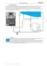
Page 9: ...ories The immersion pipe of the two ball valves should be shortened so that it ends approximately in the middle of the pipe ATTENTION Since both chemicals are mixed in with the measuring water the measuring water recirculation must occur in the direction of the flow downstream of the heat exchanger in order to prevent corrosion If the pool is being operated with an overflow gutter and a splash wat...

Page 10: ...on If the display value shows a deviation larger than 0 1pH a calibration must be conducted 6 3 Cleaning beads The enclosed blue glass beads serve for cleaning the redox electrode s platinum surface Pull the cable from the redox electrode and unscrew the electrode from the measuring cell Place approx 15 of the enclosed blue cleaning beads on the platinum surface so that this area is covered Screw ...

Page 11: ... redox status The set point of the redox voltage should then be set at approx 20 50 mV above the displayed value The development of the chlorine concentration and the redox voltage must be observed during the subsequent period and the redox voltage s set point must be increased so that the measured chlorine concentration approximates 0 5 mg l In order to avoid this uncertainty the basin water must...

Page 12: ...r metric cable glands with a jam nut are available for additional insertions The two external screw connections with M25 are intended for the insertion of a preassembled interface cable with RJ45 plug You can run the additional lines introduced by you as well as the mains supply line downward behind the measuring cell Alternatively these lines can also be run laterally below the control housing to...

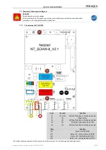
Page 13: ...ions 7 3 1 The power pack NT_SCHW 8 Fuse Current Function F1 315 mA Without function in this device series F2 2 A Primary fuse F3 1 A Without function in this device series F4 4 A 230 VAC outlet relay K2 and K3 F5 1 A Without function in this device series Plug Function SL1 Power inlet 230 VAC SL2 Relay K1 temperature 230 VAC SL3 Relay K2 disinfection 230 VAC SL4 Relay K3 pH regulation 230 VAC The...

Page 14: ...4 VDC sensors without function in the IQntrol DOS MODBUS F2 2 A Micro fuse Primary fuse power pack F3 1 A Micro fuse without function in the IQntrol DOS MODBUS F4 4 A Micro fuse 230 VDC outlet relay K2 and K3 F5 1 A Micro fuse without function in the IQntrol DOS MODBUS Relay outlets The relay outputs K1 to K3 SL2 to SL4 are non potential free 230 VAC If a potential free outlet is needed an externa...

Page 15: ...manual in German Version 1 0 2 2022 10 06 15 39 7 3 2 The I O board IO_SCHW 8 Fuses on the I O board Fuse Current Fuse type Function F1 315 mA Micro fuse Outlet disinfection 24 VDC F2 315 mA Micro fuse Outlet pH regulation 24 VDC ...

Page 16: ...e basin water 7 4 3 Temperature control The device is equipped with a temperature control This temperature control can be used to regulate the basin water temperature If the basin is heated by means of a flow through heat exchanger it must be ensured that the associated heating circuit pump may only be activated when the filter system is in operation Please remember that the regulation of the basi...

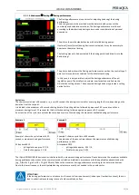
Page 17: ...uring cell flow or flow too low No flow in the clean water line to the pool or flow too low OPTIONAL if connected The dynamic dosing time monitoring has been exceeded Colour red pH regulation yellow disinfection The IQntrol DOS MODBUS has been deactivated by an external command from the swimming pool water treatment filter system There is no dosing no heating of the basin water no alarm message gi...

Page 18: ...erves for the quick viewing of the control parameters e g by the end user no changes can be made 8 1 3 Dosing delay If the device is restarted the dosing delay is running during which time no dosing occurs Software alarms are suppressed during this time The dosing delay must be set high enough to ensure that after the start of the filter system actual basin water flows through the measuring cell T...

Page 19: ...ing cell However the alarm Switch off time monitoring must be acknowledged manually 8 2 Main menu Automatic Returns to the automatic operation Settings For adjusting the control parameters and system settings Service Input and output test system information Login Password entry for authorisation The password level is displayed in the status line to the left of the date Log Event and calibration lo...

Page 20: ...rine bromine The IQntrol DOS MODBUS control is suitable for the dosing of different disinfectants The disinfection outlet must be adjusted to the disinfectant used According to the selected variant the menu for setting the associated parameters changes Alarm low lower alarm value Control range The dosing pumps work proportionally i e the higher the difference between set point and actual value the...

Page 21: ...ek days can be freely selected in this regard The dosing is done on the selected day at the selected time This should lead to a relatively even disinfectant concentration in the pool Temperature dependent additional dosing Rising basin temperatures increasingly diminish the disinfectant s efficiency For this reason it is recommended to increase the dosing volume with rising basin temperatures For ...

Page 22: ...l in the IN list This disruption can be acknowledged manually or it will be deleted following the next regular dosing Select the proper dosing times Please also consider the filter running times when setting the staring times for the O2 dosing The filter pump s running time must be selected in a way that ensures the proper distribution of the disinfectant during the filter running time and upon co...

Page 23: ...ding on the deviation from the set point It is divided into a maximum of 8 seconds dosing time for the pH regulation followed by a pause of 3 5 seconds and then a maximum dosing time of 15 seconds for the disinfection dosing followed again by a pause of 3 5 seconds An extension of the cycle time extends the second pause time thus reducing the maximum available dosing performance Example 1 Example ...

Page 24: ...l it must be considered that too short filter running times an extended voltage interruption or a device failure can lead to a failure of the pool heating This may result in frost damage to the pool For this reason it is recommended to conduct regular checks of the pool system or use other safety measures e g ice pressure cushions 8 2 1 6 Main menu Settings Dosing delay Dosing delay If the device ...

Page 25: ...lly chosen and must be a number between 00000 and 99999 To reset the Technician 1 password enter the current Technician 1 password in the uppermost Old password line enter the desired new password in both New password lines acknowledge with OK The Technician 1 password is required for the following functions Conduct a reset Delete log data Carry out extended network settings Modbus Tip Please keep...

Page 26: ...ation can be cancelled at any time with Stop For safety reasons generation of chlorine gas the output test only functions if it has been ensured that the dosed chemicals are being removed Therefore no disruption e g Measuring cell flow may be pending 8 2 2 3 Main menu Service Info Info allows you to query the currently used versions of the two firmware s DSP and IO 8 2 2 4 Main menu Service Manual...

Page 27: ...The storage depth is 50 entries Data Log In the Data Log logged measuring values can be displayed in graphs or tables The storage depth is a little over one year Export Via Export logged data can be transferred to a USB stick for data backup Delete All logged data can be deleted with Delete To delete the log data you must sign in with the Technician password 8 2 4 1 Main menu Log Event Log event l...

Page 28: ...easured values can be displayed graphically or in tabular form Data from past days can be viewed via the ICON calendar The storage depth is just over a year 8 2 4 4 Main menu Log Export Export Under the Export menu item saved log files can be loaded onto an empty USB stick for data backup If the USB stick is not empty formatting is suggested and carried out with OK confirmation You will then find ...

Page 29: ...y In case of medium deviations a cleaning notice is displayed In case of major deviations the exchange of the pH electrode is suggested If the exchange of the electrode does not remedy the problem the fault may be with the electrode cable or the measuring amplifier Notice Evaluation of the electrodes Cleaning notice At an offset voltage 61 mV the voltage value is shown in yellow and the calibratio...

Page 30: ...ltage can be chosen freely the fine tuning may also be done with other redox test solutions e g 220 mV or 640 mV When making a comparison please note the temperature dependence of the test solution See label At the end of the menu the set deviation is shown as Offset In case of minor deviations the calibration is adopted immediately In case of deviations larger than 41 mV a cleaning notice is disp...

Page 31: ...networks is required If needed please consult your network administrator who is familiar with your home network Notice We cannot assume any liability for the safety of the data transmission The evaluation of the need for and implementation of safety measures such as VPN connection password assignment and updating of the corresponding systems is the sole responsibility of the user or the persons au...

Page 32: ...eric blocks are only exemplary they must correspond to the network topology 9 2 2 IP address The transmission occurs via a static IP address this must be assigned manually The devices are not DHCP enabled automatic assignment of an IP address If multiple devices are installed in a network each device must be assigned its own IP address 9 2 3 Gateway The gateway enables the connection of different ...

Page 33: ...s in the electrode s plug head and on the electrode plug must display a shiny golden colour and may not show any signs of corrosion Each pH electrode is a wear part It is subject to a certain degree of ageing which is due to a variety of factors In the area of swimming pool water treatment the electrode should be functional for approximately 6 months to 2 years The contamination of the diaphragm m...

Page 34: ...t both dosing pumps with the test function Repeat the process twice to ensure that the chemicals are completely flushed through In conclusion pull both dosing cartridges from the motor shaft The diaphragm of a glass electrode must never dry out therefore the protective cover must be filled with a small amount of electrolyte and pushed onto the pH electrode s glass shaft The pH electrode is frost r...

Page 35: ...ing plate ready For support requests we need the exact information on the firmware currently used in the controller and the serial number of the corresponding circuit board Firmware versions Notice The above listing shows the most important cornerstones of the firmware versions including the publication date and notices about the reasons for the change Please take note of this for future orders of...

Page 36: ...er Week day Mon ml 0 ml 0 9 000 ml 50 Start 12 00 00 00 21 00 10 Temperature 24 19 30 1 Week day Tue ml 0 ml 0 9 000 ml 50 Start 12 00 00 00 21 00 10 Temperature 24 19 30 1 Week day Wed ml 0 ml 0 9 000 ml 50 Start 12 00 00 00 21 00 10 Temperature 24 19 30 1 Week day Thu ml 0 ml 0 9 000 ml 50 Start 12 00 00 00 21 00 10 Temperature 24 19 30 1 Week day Fri ml 0 ml 0 9 000 ml 50 Start 12 00 00 00 21 0...

Page 37: ...0 C 0 1 Control range 1 C 0 1 10 K 0 1 Alarm low 10 C 1 50 C 0 1 Alarm high 30 C 15 55 C 0 1 Offset off 5 C 5 C 0 1 Control On Off On Dosing delay Dosing delay 600 seconds 10 600 sec 10 System Password End user 0000 9999 1 Technician 1 01234 00000 99999 1 System Display Screensaver 20 12 100 2 Delay 00 05 minutes 00 00 23 59 1 Backlight 75 24 100 2 System Network IP address 192 168 0 1 Gateway 192...

Page 38: ...enance set for flow controller 0010480 Filter cup transparent standard filter 0010481 Filter cup gasket standard filter 0010482 Filter element 300 µ standard filter 0015077 Tube PVC 4 x 1 mm by the metre 0010435 Tube PE 6 x 1 mm by the metre 0010433 Tube PTFE 6 x 1 mm by the metre 0012031 Ball Valve d20 6 x 1 mm Electrodes Item number 0010933 pH electrode PG13 5 60 mm standard 0011984 Redox electr...

Page 39: ...Sa blue 0013482 Hose set Sa 0 8x1 6 Ph blue marking 0013412 Hose set Sa 1 6x1 6 Ph black marking 0013413 Hose set Sa 3 2x1 6 Ph green marking 0024871 Fine filter 300 µ 6x1 complete design upon request 0021531 Temperature sensor 6 x 50 mm 2 m line length special length with 12910 for external installation 0012910 Temperature sensor sleeve PVC x 60 mm for external installation 16 Personal notes You ...

Reviews: