Assembly and Operation Manual
8.4 Installation
Further installation instructions are given with the earlier mentioned recommendations (see
Clause 8.1) taken into account. Recommendations on preparation of mounting holes in the
mounting surface are given with regard to
“SORMAT”
PFG IR 10 anchor bolts for solid
concrete floors.
1. Unpack the card capture reader, check the delivery set completeness.
2. The card capture reader is placed at an exit from the territory before the OD.
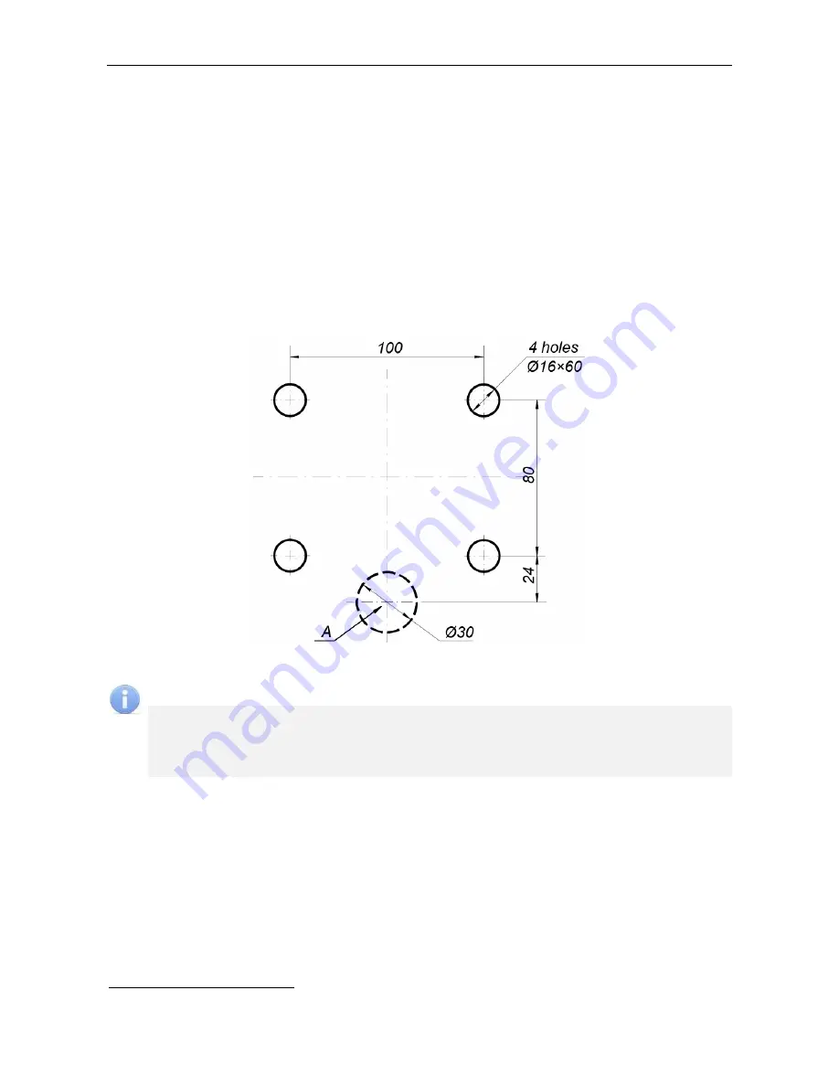
3. Mark out mounting holes following Figure 5 on the mounting surface for the card
capture reader installation, as well as mark electric raceways for the power cable
(10)
1
,
cable for connection an ACS controller (11)
1
and cable (12)
1
for the reader’s
data lines connection to
A
zone of the cables input to the card capture reader with
regard to location of the power supply, ACS controller and OD.
Figure 5. Floor anchor position and cable entries (A) for IC-02.1 housing installation
Note:
Material, configuration, dimensions, wiring type (surface, buried, combined), position
at the entrance point and other characteristics of the electric raceways
are chosen
by the customer
in accordance with the entrance point features and layouts, other
operational factors.
4. Prepare the electric raceways and mounting holes for the card capture reader
installation. Set the anchors all the way down the prepared holes.
5. Carefully lift up the cover (4) and slightly move it for access to two screws fixing the
panel (3). When moving the cover do not disconnect the reader cable. Release the
screws and take off the panel (3).
6. Place the card capture reader on the mounting surface so that its base (1) was near
A
zone (see Figure 5).
7. Through the central hole
30 mm in the base (see Figure 6) pull cables (10), (11)
and (12) inside the card capture reader in the back panel direction and further up
1
Cables (10), (11) and (12) are not included in the standard delivery set.
12


