IC-02.1 card capture reader
5.2 Design
The design of the card capture reader is shown in Figure 2. Numbers of the items
hereinafter refer to the item numbers as shown in Figure 2.
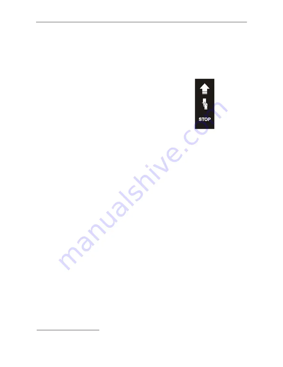
The cover (4) houses: on the external side – an indication module (5) with 3 mnemonic
indicators, (shown in Figure 3), on the internal side – a reader (a control board without
casing with an antenna). The cover has a slot (6) for cards capturing.
Green indicator - authorization of passage
→
Yellow indicator - the passage waiting
(standby card presentation)
→
Red indicator - the prohibition passes
→
Figure
3. Mnemonic indicators display unit
Panel (3) is fixed to the housing
(2) with screws, that when taken of gives an access to the
units that ensure operation of the card capture reader:
card capture reader control board that is located in its upper part from the panel’s
side;
electric drive with a shutter (7) that prevents card falling into the card container;
shutter position optical sensors;
card position optical sensors, the fact of capturing and overfilling of the container.
5.3 Power supply
The card capture reader is powered from a DC power supply with 12
±
1.2 V
voltage. The
card capture reader can either be connected to a separate power supply or parallel to the
ACS controller to the general power supply.
When choosing power supply unit make sure it provides a 30% reserve of the
consumption current. Maximum consumption current of the card capture reader is 1 A.
Maximum consumption current of the ACS controller is given in its certificate.
Power cable (9)
is connected to the connector block
XT6
of the card capture reader
control board (see Figure 4).
Cable (9) is not included in the set of delivery.
7


