Assembly and Operation Manual
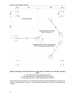
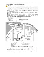
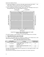
Figure 4. Hole pattern for mounting of the canopy posts (3) relative to the turnstile mounting
holes:
A
– mounting point of the turnstile barrier section.
L
– mounting point of the turnstile left guide barrier section.
R –
mounting point of the turnstile right guide barrier section.
Figure 4 shows a sketch layout of the turnstile mounting holes. Exact coordinates of the holes in A,
L
and
R
mounting points are given in the
Operational Manual to the RTD-15 Full Height Rotor
Turnstile.
8
Summary of Contents for RTC-15.3
Page 1: ...ASSEMBLY AND OPERATION MANUAL WARRANTY CARD RTC 15 3 Protective Capony...
Page 2: ...Protective Canopy RTC 15 3 Assembly and Operation Manual Warranty Card...
Page 15: ......
Page 16: ......
Page 18: ...www perco com...


