ST-02 Speed gate and STD-02 Double-sided section
23
8.3 Cable length
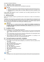
The cables used for installation are shown in Table 3.
Table 3. The cables used during installation
№
Equipment
Cable
length, m,
max
Cable type Crossection,
mm
2
, min
Cable example
1 Speed gate power
supply
10
Twin wire
1.5
AWG 15;
HO5VV 2×1.5 two-tone
20
Twin wire
2.5
AWG 13;
HO5VV 2×2.5 two-tone
2
- Fire
Alarm Device
- Optional equipment to
input or output of the
control board
30
Twin wire
0.2
RAMCRO SS22AF-T
2×0.22
CQR-2
3 RC-panel
40
Eight core cable
0.2
CQR CABS8 8×0.22 c
4 ACS controller
30
Six core cable
0.2
CQR CABS6 6×0.22 c
8.4 Installation procedure
Attention!
The manufacturer is not responsible for damages that were caused because of improper
installation and will reject any claim if the installation is not carried out in accordance with
the instructions given in this operating manual.
The installation operations are given with regards to recommendations described in section.8.1,
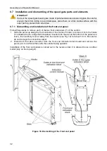
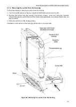
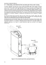
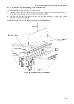
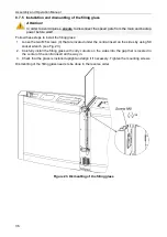
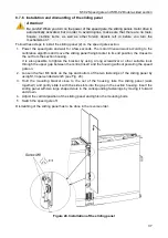
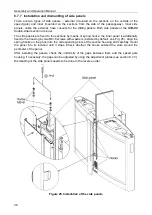
detailed installation and dismantling of individual parts of the speed gate are described in section
8.7. Equipment and tools required for installation are listed in the section 8.2. The types of cables
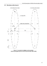
used for installation are listed in section 8.3. Marking layout of the installation surface is given in
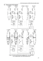
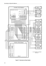
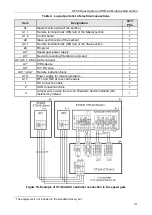
sect. 8.5. Wiring diagrams are given in section 8.6.
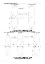
Item numbers are shown in accordance with Fig. 3 and 4.
Attention!
•
The speed gate sections are heavy. Moving of the speed gate sections should be
carried out only with the use of the mounting tool, use the special clamps located at the
front ends of the section under the front end panels, do not try to lift them by holding the
glass top covers or other elements of the housing!
•
Installation and fastening of the speed gate sections should be carried out after routing
of all cables in cable channels and within sections.
•
Be especially careful and protect the sections as well as parts of the sections from
falling in order to prevent from damage while your disassembly the parts of the speed
gate sections before they are fixed on the mounting surface.
Follow the next steps during installation procedure
:
1.
Install the power supply into the place in accordance with its service documentation.
2.
Determine locations for the
Master
and
Slave
sections and, if necessary, determine locations
for the double-sided sections. It is necessary to pay attention to the mutual arrangement of
sections: you should always place the panel of the
Master
section (side of the double-sided
section) towards the panel of the
Slave
section (side of the double-sided section).
Master
or
Slave
side of the double-sided
STD-02
section can be identified by means of stickers located
under the side panels (6).
1
The Video Guide section on the website
contains video guide on assembly and installation of
ST-02.


