ST-02 Speed gate and STD-02 Double-sided section
25
11. Check the vertical position of the section with level, the vertical deviation of the section in the
X-axis should not exceed 0.5 º. Use the special screws at the base of the section for
alignment (you will need to remove the section from the base to access them). It is allowed to
use mounting gaskets.
Note:
The following paragraphs 12 – 14 should be carried out during installation of the additional
STD-02
double-sided section.
12. Unpack and install the double-sided section. Follow the actions specified in Sections 7 – 11,
align the double-sided section so that its
Slave
side (indicated on the sticker) is placed
towards the
Master
section.
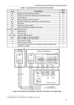
13. Route cables inside section used for controlling the second passage lane. The hole for cable
entry is located at the base of the double-sided section (from the side of the
Master
section):
from the power supply, from the RC-panel or ACS controller, from the
Fire Alarm
device and
optional equipment, as well as DC and CAN cables of the
Slave
section.
14. If necessary, install other double-sided sections (paragraphs 14 to 16).
15. Unpack and install the
Slave
section (
ST-02/S
, boxes No.3 and No.4). Follow the steps
specified in paragraphs 7 - 11.
Note:
The following paragraphs 16 to 21 shall be carried out for each individual passage lane.
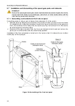
16. Remove the two screws that secure the terminal blocks to the bottom of the
Master
and
Slave
sections (sides of the sections) to the housing (see Fig. 5 ), and take them out, be
careful – do not damage the internal wiring that leads to the terminal blocks!
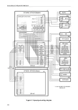
17. Take out the external connection cables from the inside of each section (the sides of the
section) and connect them to the remote terminal block in accordance with the speed gate
wiring diagram (see Fig. 17). Mount and secure the remote terminal block. Carefully lay down
the connected cables inside the housing of the section.
Note:
DC and CAN connection cables are connected to the remote terminal block of the speed
gate sections in accordance with the core marking.
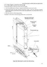
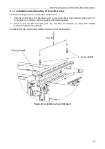
18. If necessary, install the access card reader and ACS controller – card readers are mounted
on special brackets located inside of the sections under the top indication blocks or directly
on the bottom of the indication blocks (
MR07 OEM
); the ACS controller is mounted in the
opening of the section housing, under the speed gate top cover by means of self-adhesive
clips from the delivery set (see Fig. 20).
Attention!
By default, it is possible to install the
PERCo
access card reader and ACS controller inside
of the speed gate section.
Third-party hardware must meet the following requirements:
−
overall dimensions of ACS controller,
(length × width × height) ....................................................... max. 160×140×40
mm
−
reader overall dimensions,
(length × width × height) ......................................................... max. 230×72×32
mm
−
passage sensors reading range ................................................................. min 40
mm
(
stable reading of the cards is not guaranteed in cases when the reading range of
the installed readers is less than 40 mm
).
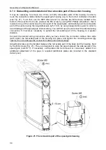
In order to increase the reading range, the readers should be as close to the top surface of
the speed gate glass cover as possible. To do this, you can adjust the height of the bracket
by using two screws (located under the shelf bracket). For more precise adjustment, it is
recommended that the cover (3) with the top indication block is temporarily installed in its
place and the front end panel is removed (7).


