ST-02 Speed gate and STD-02 Double-sided section
39
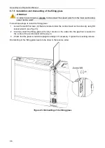
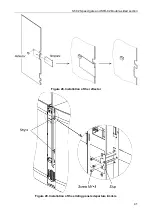
8.7.8 Installation and dismantling of glass covers
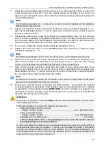
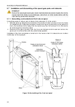
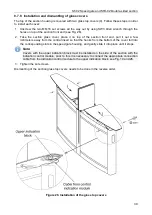
The top of the section housing is covered with two glass top covers (4). Follow these steps in order
to install each cover:
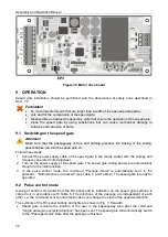
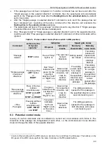
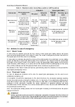
1. Unscrew the two M6×16 set screws all the way out by using SW3 Allen wrench through the
holes on top of the section front end (see Fig. 26).
2. Take the section glass cover, place it on top of the section front end, pull it out a few
millimeters away from the central insert so that the hooks from the bottom of the cover fall into
the corresponding slots in the speed gate housing, and gently slide it into place until it stops.
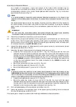
Note:
Covers with the upper indication block must be installed on the side of the section with the
indication control module, prior to this it is necessary to connect the appropriate connection
cable from the indication control module to the upper indication block, see Fig. 19 and 26.
3. Tighten the set screws.
Dismantling of the section glass top covers needs to be done in the reverse order.
Figure 26. Installation of the glass top covers

