Assembly and Operation Manual
42
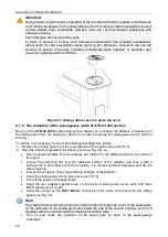
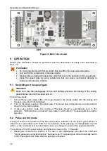
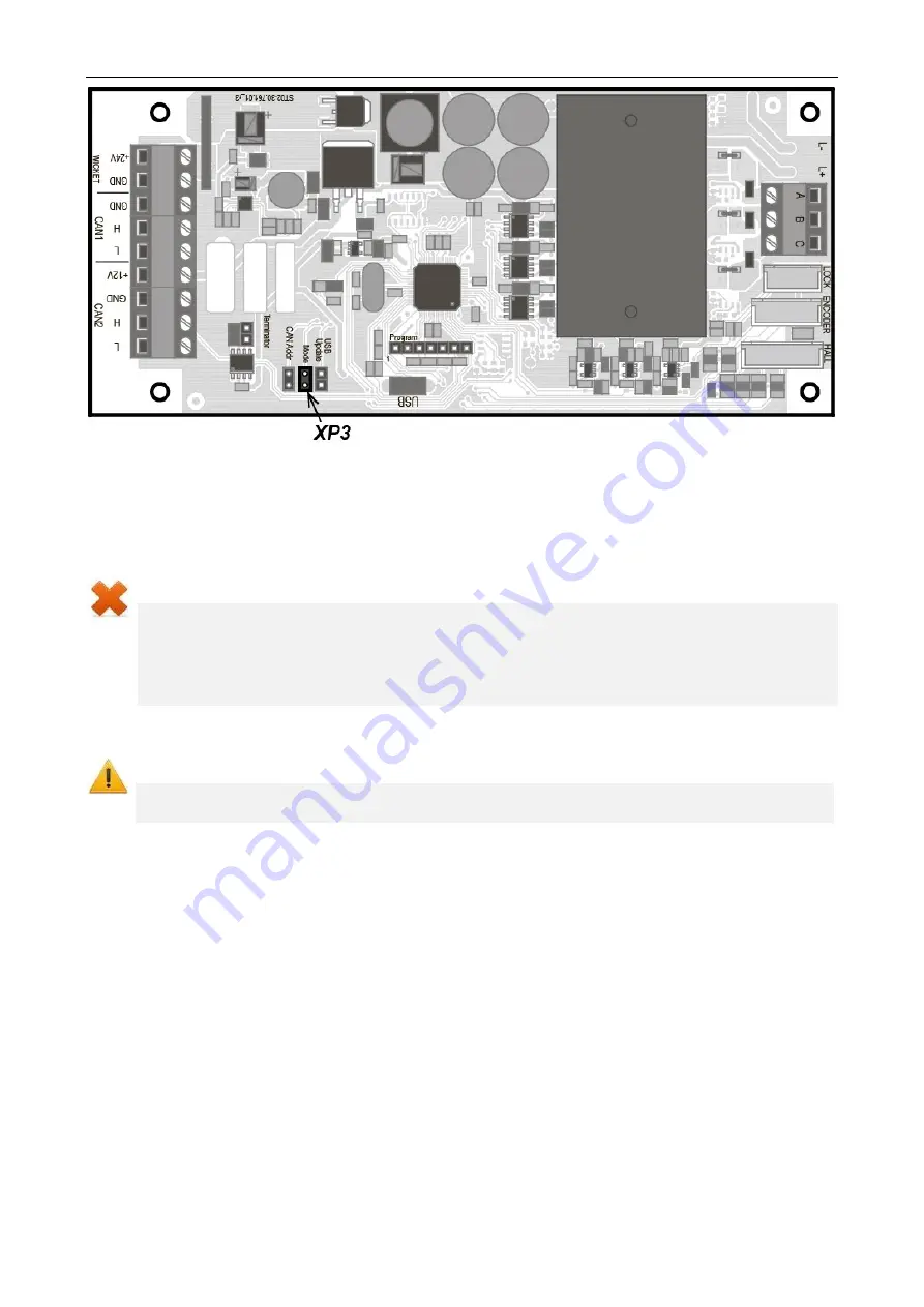
Figure 30. Motor drive board
9 OPERATION
Speed gate installation should be performed with the observance of safety rules described in
Sect. 7.2.
Forbidden!
•
To move objects through that are larger than a width of the opened passageway.
•
Jerk and hit the components of the speed gate.
•
Disassemble and adjust the assembly units that ensure the operation of the speed gate.
•
Clean the speed gate by using substances that can cause mechanical damage to
surfaces and corrosion of parts.
9.1 Switching on the speed gate
Attention!
Make sure that the passageway is free and nothing prevents the closing of the sliding
panels before you turn the speed gate on.
Follow these steps:
1. Connect the power supply cable of the speed gate to the mains socket with the voltage and
frequency specified in its datasheet.
2. Turn on the power supply of the speed gate. The speed gate sliding panels are automatically
brought to the initial position.
3. In the pulse control mode, the command
"Passage denial"
is automatically sent, in the
potential –
"Both directions are locked"
(see Table 5 and Table 6) The speed gate is ready for
operation.
9.2 Pulse control mode
Issuing of control commands from the RC-panel and its indication on the speed gate sections is
carried out in accordance with Table 5. The directions of the passage are independent of each
other, i.e. the command sent to one direction does not change the state of the opposite direction.
The symbols of the RC-panel buttons and lights are shown in Fig. 7. Herewith:
•
Speed gate monitors the location of the user in the passageway area after the command
"Single passage in selected direction"
has been sent. The speed gate will automatically switch
to the
"Passage denial"
state after the passage is finished.

