TTR-04CW-24 Electromechanical Tripod Turnstile
9
WARNING!
To avoid accidental power-up of the SPS during storage or transportation, a
“Bat/2
А
” fuse is not installed and is provided together with a set of spare parts.
The CU front panel has the following LED indicators (Fig. 2):
“Power”
– AC mains on green;
“12V”
– 12V DC power supply, green;
“Battery”
– the CU changeover to the SPS and indication of the SPS battery
discharge, red;
“Mode” –
in this modification is not used
CU front panel also houses:
“Power”
“ON”/”
О
FF”
toggle switch – AC mains switching ON/OFF;
“
Battery” ”Internal”/”External”
toggle switch – connection of the internal SPS or
external DC power supply.
The CU lower panel contains:
3 fuse slots with fuses installed (0.5A — 2 pcs., 2A — 1 pc.);
AC power input cable connector
“Power”
;
RC panel connector “
RC”;
connector for access control system “
ACS”;
turnstile housing connector
“
С
ontrol”;
external power supply connector
“
В
at=12V”;
wireless control connector “
Wireless”.
5.3 Control over turnstile
The turnstile can be operated:
from the RC panel;
from an ACS.
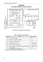
For connection layout please refer to Fig. 8 (see Appendix).
5.3.1 Control with the remote control panel
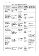
The following operating modes can be set from the RC panel (see Table 1):
“
Always locked
”
“
Single passage in the set direction
”
“
Bi-directional single passage
”
“
Free passage in the set direction
”
“
Free passage in one direction, single passage in the opposite direction
”
“
Always free
”
5.3.2 Operation from an ACS via the CU
“
ACS
”
connector
ACS is connected to the CU
“
ACS
”
connector with a cable. The turnstile control is effected
in a pulse mode (similar to the one via the RC panel). The
“
ACS
”
connector pins
assignment is shown in Fig. 3.
The turnstile is operated from the CU
“
ACS
”
connector by closing the contacts
“
RIGHT
”
,
“
STOP
”
,
“
LEFT
”
and
“
GND
”
(GROUND) or by input of a low-level signal. As the control
element in the ACS there can be used a normally open relay contact or a circuit with open
collector output and the following signal features:
permanent or impulse low-level signals with duration ...................no less than 100 ms
the voltage at open contact ...............................................................................5±0.5 V
the voltage at closed low-level contact ........................................... no more than 0.8 V
the current via closed contact...................................................... no more than 1.5 mA
Summary of Contents for TTR-04CW-24
Page 1: ......
Page 2: ...Electromechanical Tripod Turnstile PERCo TTR 04CW 24 Assembly and Operation Manual...
Page 24: ......
Page 26: ...www perco com export perco ru...


