Assembly and Operation Manual
16
9 OPERATION INSTRUCTIONS
Attention!
Observe general electrical safety requirements during the turnstile operation.
WARNING! It is prohibited:
to use abrasive or chemically active substances for cleaning the external
surfaces;
to move through the turnstile passage area any objects with dimensions
exceeding the width of the passageway;
to jerk or hit the barrier arms and surfaces so as to prevent their mechanical
deformation.
9.1 Power-up
1. Necessarily lock the turnstile with the mechanical release key (9).
2. Check the accuracy of all the connections and the power supply cable operability.
3. set up the
“Power”
toggle switch and the
“Battery”
toggle switch to the
OFF
and
to the
External
positions accordingly Fig. 2).
4. Put the “Bat/2A” fuse that is included in the CU spare parts kit in its place.
5. Connect the AC power cable (8) (Fig. 1) of the CU (3) to the 220V / 50Hz AC outlet.
WARNING!
Do not connect the control unit to the mains with the voltage and frequency rating
other than specified in Chapter 3 of this Manual.
6. Set the
“Power”
toggle switch and the
“Battery”
toggle switch to the
ON
and the
Internal
positions accordingly. At the same time the indicators (13)
“Power”
and
“12V”
on the CU (3), the pictogram “Red cross” on the LED indication display (12)
of the turnstile housing (1) and the indicator above the
STOP
button on the RC
panel (4) will light up.
9.2 Operating modes set from the RC panel
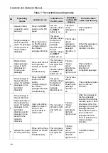
The turnstile operating modes set from the RC with the corresponding indication are
described in Table 1.
It is important to take into account that:
After its power-up the reset state of the turnstile is “Closed for entry and exit”;
Setting the operating modes for each direction is independent: setting the operating
mode for one direction does not change the operating mode set earlier on for the
opposite one;
The “Single passage in the set direction” mode can be changed to the “Free
passage” mode for the same direction, or to the “Always locked” mode;
The “Free passage in the set direction” mode can be changed to the “Always
locked” mode only.
In the “Single passage in the set direction” operating mode the turnstile is automatically
locked after a person’s passage in the set direction. If the passage is not effected within
the passage waiting time (this time is preset and equal to 5 seconds), the turnstile is also
locked automatically. In the “Bi-directional single passage” mode, after the passage in one
direction the count-up of the passage waiting time (5 seconds) for the opposite direction is
recommenced.
Summary of Contents for TTR-04CW-24
Page 1: ......
Page 2: ...Electromechanical Tripod Turnstile PERCo TTR 04CW 24 Assembly and Operation Manual...
Page 24: ......
Page 26: ...www perco com export perco ru...


