background image

TTR-04CW-24 Electromechanical Tripod Turnstile  

17 

If the barrier arms do not reset to home position after the start of rotation within  
5 seconds, the RC panel starts generating audio signals. It stops signaling when the 
turnstile gets back to the reset state. 

9.3  Operation with the built-in SPS 

In case of the AC mains failure the turnstile remains in operation and turns to the SPS built 
into the CU. When operating with the SPS, the 

“Battery” 

indicator on the CU is on. The 

signal 

“Pwr failure”

, notifying of the AC mains failure, is transmitted to the CU 

“ACS”


connector. There will be intermittent indication (with blinking interval of 0.5 seconds) on the 
LED indication display of the turnstile housing and on the RC 
At the SPS battery discharging up to the level of 11 V, the 

“Battery”

 indicator starts 

blinking (becomes dim for short time periods) warning about the discharge. The signal 

“Bat failure”

 generates at the CU 

“ACS”

 connector

At the battery discharging up to the level of 10.4 V, the turnstile turns to the “Always 
closed” mode; the LED indication display is out; the blinking mode of the 

“Battery”


indicator and of the red indicator on the RC changes to infrequent flashes. 
In the emergency mode the turnstile can be locked and unlocked only with the mechanical 
release key (10) (Fig. 1).  
When the AC mains is restored, the turnstile returns to normal operation from the AC 
mains. The built-in SPS battery will recharge automatically if the 

“Battery”

 toggle switch is 

in the 

Internal 

position. 


Attention! 

Operation time with the built-in battery is no less than 4 hours in the “Always closed” 
operating mode or 1,000 passages provided that the battery is fully charged.  
The CU SPS contains a lead-acid battery, which is not recommended to be stored 
for a long time without recharging. For recharging during the storage period the CU 
must be switched on for 6 – 12 hours every 8 months (every 2 months when stored 
at ambient temperature above +30°C). The sequence of actions is given in 
Clause 9.1. There is no need to connect the turnstile housing and the RC to the CU 
at that. 

Summary of Contents for TTR-04CW-24

Page 1: ......

Page 2: ...Electromechanical Tripod Turnstile PERCo TTR 04CW 24 Assembly and Operation Manual...

Page 3: ...he turnstile with a mechanical release key 11 6 MARKING AND PACKAGING 12 7 SAFETY REQUIREMENTS 12 7 1 Installation safety requirements 12 7 2 Operation safety requirements 12 8 INSTALLATION INSTRUCTIO...

Page 4: ...outlets railway terminals airports etc To ensure fast and convenient passage it is recommended to install one turnstile per 500 people working the same shift or on the basis of maximum working load 30...

Page 5: ...ontrol unit power cable 1 5 m RC panel cable 3 m Turnstile housing in assembly net weight max 37 kg Control unit net weight max 3 8 kg Throughput rate in a free passage mode 60 persons min Throughput...

Page 6: ...Plastic plug 4 Operational documentation Certificate 1 Operation manual 1 Packaging Box 1 Spare parts Plastic plug 1 Fuses 1 1 250 0 5 2 1 1 250 2 1 ACS connector DBH 15F cable socket 1 H9 connector c...

Page 7: ...le housing cable 8 AC power cables 9 mechanical release key 10 lock 11 hub 12 cover with LED indication display 13 CU indicators 14 rotation mechanism 15 dowel 16 anchor bolt 10 70 17 screw 4 20 18 fa...

Page 8: ...an upper part of the turnstile housing there is a rotation mechanism 14 with three barrier arms 2 a locking device a self centering mechanism and arm rotation sensors A LED indication display is locat...

Page 9: ...housing can be changed by switching the RC panel over to the Wireless connector of the CU Fig 2 The RC panel is equipped with a buzzer for audio signal generation Button push signals from the RC pane...

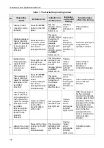
Page 10: ...rated from the RC panel from an ACS For connection layout please refer to Fig 8 see Appendix 5 3 1 Control with the remote control panel The following operating modes can be set from the RC panel see...

Page 11: ...d Sens L Pass L contacts is changed at passage in the opposite direction NOTE The variant of signal generation is set by the jumper on the J3 connector for the J3 connector location see label inside t...

Page 12: ...s 5 4 Unlocking of the turnstile with a mechanical release key The key 9 of the mechanical lock 10 is intended for unlocking of the turnstile in case of emergency or power failure at the AC mains swit...

Page 13: ...Manual Warning Use only the serviceable tools for installation Observe general electrical safety rules when laying out the cables All the connectors should be connected up when the CU is switched off...

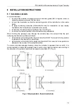
Page 14: ...ntrol the vertical position of the turnstile during installation When forming the passage area through the turnstile take into account that the self centering mechanism operates as follows at the barr...

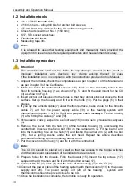
Page 15: ...Put the plugs 5 in their places 4 If you lay the turnstile cable 7 under the floor surface make a hole for the turnstile cable 7 and for the power supply cable 19 of the heating system with thermocont...

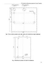
Page 16: ...TTR 04CW 24 Electromechanical Tripod Turnstile 15 Fig 5 Floor anchor position and cable entries for turnstile housing installation Fig 6 Wall dowel position for the CU installation...

Page 17: ...e same time the indicators 13 Power and 12V on the CU 3 the pictogram Red cross on the LED indication display 12 of the turnstile housing 1 and the indicator above the STOP button on the RC panel 4 wi...

Page 18: ...At the battery discharging up to the level of 10 4 V the turnstile turns to the Always closed mode the LED indication display is out the blinking mode of the Battery indicator and of the red indicator...

Page 19: ...t are on The turnstile is locked in the direction of completed passage 4 Free passage in the set direction open for multiple passages in the permitted direction Press the STOP button and the button co...

Page 20: ...ower panel The CU Power indicator is on but the 12V indicator is off The RC generates continuous audio signal The 12V 0 5 is burnt out likely due to external short circuit Disconnect the CU from the A...

Page 21: ...a qualified mechanic who has studies carefully this Manual Prior to the turnstile maintenance works disconnect the CU power supply from the AC mains set up the Power toggle switch to the OFF position...

Page 22: ...sensors 5 Connect the cable header of the indication board to the control mechanism connector and mount the cover with LED indication display 12 back into its place in the reverse order to the disman...

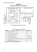
Page 23: ...e Q ty Note A1 Control unit CU 02N 1 A2 Remote control panel H 06 4 100 1 A3 Turnstile housing T 04W 24 1 A4 Wireless remote control 1 MSRF 4 A5 Power supply of the turnstile 1 12V 1 2 A6 Power supply...

Page 24: ......

Page 25: ...PERCo P O Box 87 Saint Petersburg 194295 Russia Tel 7 812 321 61 72 Fax 7 812 292 36 08 E mail export perco ru support perco ru www perco com...

Page 26: ...www perco com export perco ru...

Reviews: