TTR-04CW-24 Electromechanical Tripod Turnstile
7
5 PRODUCT DESCRIPTION
5.1 Main features
The turnstile can be operated from the RC panel or by a WRC, as well as from an ACS.
The turnstile housing is supplied with a safe voltage — no more than 14 V, with the
heating system with thermocontrol in operation — no more than 40 V.
The turnstile has low power consumption — maximum 20 W, with the heating system
with thermocontrol in operation – maximum 80 W total.
The standby power supply (the SPS) built into the control unit is provided with a lead-
acid backup battery to maintain proper operation of the turnstile for 4 hours or 1000
passages in case of the power failure. Once the main power is restored, the battery
automatically starts being recharged.
The turnstile retains the set position for each direction when the power supply voltage
is removed – an open passage direction remains open, a closed passage direction
remains closed.
After each passage the turnstile provides automatic complete rotation of the barrier
arms to home position, i.e. automatic reset.
Smoothness of reset and quiet operation are ensured by a damper.
Optical arm rotation sensors are built into the turnstile housing to ensure accurate
count of inputs to an ACS.
The mechanical release lock built into the turnstile housing ensures the turnstile
unlocking with a key in emergency cases (free rotation of barrier arms).
5.2 Design
The design of the turnstile is shown in Fig. 1.
The turnstile housing (1) is a welded metal structure with a cover (12). In an upper part of
the turnstile housing there is a rotation mechanism (14) with three barrier arms (2), a
locking device, a self-centering mechanism and arm rotation sensors. A LED indication
display is located on the front panel of the cover (12). The turnstile
housing is equipped
with the heating system with thermocontrol.
The large LED indication display with bright pictograms is intended for status and direction
indication: a Green Arrow indicates the direction of an authorised passage (the turnstile is
open in the set direction); a Red Cross indicates ban on passage (the turnstile is locked).
In the left-hand bottom corner of the LED indication display of the turnstile
housing there is
an additional LED indicating operating modes of the built-in heating system with
thermocontrol. The LED is green when the heating system with thermocontrol is powered
up, and it is amber when the heater is in operation.
The turnstile housing (1), the control unit (3) and the remote control panel (4) are
connected with cables (6, 7).
The remote control panel (the RC panel) is designed as a small desktop device with a
shockproof ABS plastic case and is intended for setting and indicating operating modes
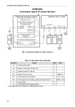
when the turnstile is operated manually. The RC panel is connected to the control unit (the
CU) with a multicore flexible cable (6) via the “RC” connector (Fig.2).
There are three control buttons on the RC front panel, which are intended for setting the
turnstile operating modes. Above the buttons there are LED indicators. The button in the
middle (hereinafter – the
STOP
button) is intended to set the turnstile to the “Always
locked” mode. The left and the right buttons are intended to unlock the turnstile for
passage in the chosen direction.
Summary of Contents for TTR-04CW-24
Page 1: ......
Page 2: ...Electromechanical Tripod Turnstile PERCo TTR 04CW 24 Assembly and Operation Manual...
Page 24: ......
Page 26: ...www perco com export perco ru...


