TTR-08A Electromechanical Tripod Turnstile
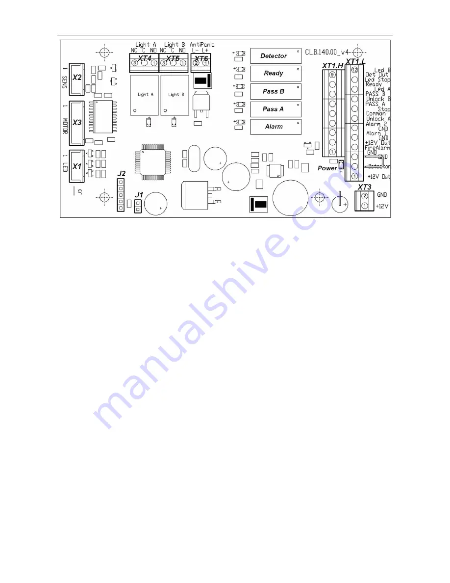
Figure 4. Control Logic Board (CLB)
The CLB (Fig. 4) includes:
X1
(
LED
),
X2
(
SENS
),
X3
(
MOTOR
) connectors to connect the indication module,
optical arm rotation sensors and control mechanism with a locking device (from the
X1, X2, X3 connectors with the turnstile cable);
XT1.L
(
In
) connector block to connect the RC panel / WRC / ACS controller inputs
as well as an emergency unblocking device (
Fire Alarm)
and intrusion detector;
XT1.H
(
Out
) connector block to connect a siren and ACS outputs, providing the
turnstile status data to the ACS controller;
XT3
(
+12VDC
) connector block to connect the turnstile power supply;
XT4
(
Light A
) and
XT5
(
Light B
) connector blocks to connect “open/closed” remote
indicators, one indicator per each direction;
XT6
(
AntiPanic
) connector block to connect the electromagnet of automatic
anti-panic unblocking device;
J1
connector to select the turnstile control mode, the jumper is fixed — the pulse
control mode, the jumper is not fixed — the potential control mode. The jumper is
fixed at the factory before the delivery
J2
connector for programming.
Power
– power LED indicator on the control board.
5.3 Control devices of the turnstile
The turnstile can be operated from the following control devices:
the RC panel;
the
WRC;
the ACS controller.
The above devices can be connected to the turnstile as follows:
any
device
separately;
in any combination with each other;
all devices simultaneously (in parallel).
9
Summary of Contents for TTR-08A
Page 34: ...www perco com...


