TTR-08A Electromechanical Tripod Turnstile
Figure 5. ACS control element — normally open relay contact
Figure 6. ACS control element — circuit with open-collector output
The relays PASS A (contacts
PASS A
and
Common
),
PASS B
(contacts
PASS B
and
Common
),
Ready
(contacts
Ready
and
Common
),
Detector
(contacts
Det Out
and
Common
) and
Alarm
(contacts
Alarm 1
and
Alarm 2
) have normally open contacts. The
“
Common
” contact, at that, is not connected to the CLB power supply negative terminal.
In the initial (inactive) state, when the power is on, the relay contacts “
PASS A
”, “
PASS B
”,
“
Ready
” and “
Detector
” are closed (voltage is supplied to the relay coil) and the “
Alarm
”
relay contacts are broken (voltage is not supplied to the relay coil).
The CLB relay operation/release is indicated by lighting up/going down of the red test
indicators located near the corresponding relays (Fig. 4).
The output cascades for
PASS A
,
PASS B
,
Ready
,
Det Out
and
Alarm
are the contacts
with the following signal characteristics (Fig. 7):
maximum commutation voltage...................................................................... 42V DC
maximum switched current................................................................................ 0.25A
closed contact resistance ...................................................... no more than 0.15 Ohm
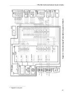
Figure 7. Output cascades for PASS A, PASS B, Ready, Det Out and Alarm
11
Summary of Contents for TTR-08A
Page 34: ...www perco com...


