Assembly & Operation Manual
Horn-type and socket wrenches: S17, S13 and S10;
Set square 90º;
Allen key S3;
Level;
Measuring tape (2 m);
Hard wire 1.5 m long for cable pulling;
Slide
caliper.
Note:
It is allowed to use other testing equipment and measuring tools provided
the equipment in use ensures the required parameters and measurement accuracy.
8.3 Length of cables
Table 1. Cables, used at the installation
№
Equipment
Cable
length, m,
max
Cable type
Cross-
section,
mm, min
Example
10
Twin cable
1.5
AWG 15; HO5VV-F 2×1.5
1 Power supply
15
Twin cable
2.5
AWG 13; HO5VV-F 2×2.5
2
-
Fire Alarm
- Optional equipment to control
board input and output
30 Twin
cable
0.2
RAMCRO
SS22AF-T 2×0.22
CQR-2
3 RC panel
40
Eight core cable
0.2
CQR CABS8 8×0.22c
4 ACS controller
30
Six core cable
0.2
CQR CABS6 6×0.22c
8.4 Installation procedure
Caution!
The Manufacturer does not incur liability for the damage to the turnstile and other
equipment and other losses resulting from the turnstile incorrect installation and no
claims from the Customer are accepted if the installation is made without following
the instructions of the given Manual.
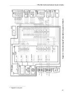
The turnstile connection layout is given in Fig. 12. The CLB connectors location is shown
in Fig. 4. Cables parameters and their length are given in clause 8.3. The installation
surface and passage area recommendations are given in clause 8.1.
1. Unpack the turnstile check the completeness as per Chapter 4.
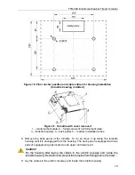
2. Make the holes for anchor bolt (15) sleeves for the turnstile housing installation
(Fig. 10).
3. Install the turnstile power supply unit (9) in its place (See power supply unit
certificate for installation procedure of the turnstile power supply).
4. If you lay out cables under the floor surface, make an electric raceway to the cables
entry zone of the turnstile housing (shown in Fig. 10).
5. Insert sleeves for anchor bolts into the holes so that they do not stick out above the
floor surface.
6. Remove the cover (2) in order given in Chapter 6.
7. Remove the reinforcement plate (see Fig. 11). To do so first loosen 4 fixing screws
of the plate with the flat slot screwdriver.
18
Summary of Contents for TTR-08A
Page 34: ...www perco com...


