Assembly & Operation Manual
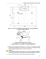
10. Install the turnstile housing on anchor sleeves and fix it with M10 bolts using S17
socket wrench. Check the position of the housing with the level.
11. If it is necessary to set up the turnstile into potential control mode remove the
jumper on the
J1
connector of the CLB.
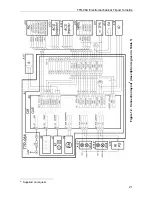
12. Connect the RC panel cable (14) (WRC / ACS controller) to
XS1
connector block.
13. Connect the additional equipment if necessary (intrusion detector and a siren;
emergency unblocking device (
Fire Alarm)
; remote indicators).
14. Connect the power cable
(11) from the turnstile power supply
to
XS1
connector
block.
15. If needed, install the proximity card readers into the special places, situated in the
housing (5 in Fig. 11). To connect card readers use free contacts (15 - 24) of the
XS1
connector block.
Caution!
In order to install readers, manufactured by other companies, please note that they
are to comply with the following characteristics:
dimensions (length × width × height) ..................................... max 145×90×25 mm
card reading distance ........................................................................... min 70 mm
In case of use of card readers with read range fewer than 7cm, the steady reading
of cards during their validation is not guaranteed
5
.
16. Check serviceability and accuracy of all the electrical connections. Fasten all the
cables in two points to the hole in the turnstile housing horizontal plane, using hook
and loop cable ties.
17. Install the back panel in reversed order.
18. Install the reinforcement plate on the turnstile in reversed order.
19. Connect the indication board cable header to the
S1
connection slot.
20. Mount the cover with LED indication back into its place in the reverse order. When
the cover with LED indication mounting is carried out correctly it does not need
much effort. Fasten the cover with the bolts.
21. Install the hub (5) with the barrier arms (3) in the following order:
Insert the hub into a corresponding mounting face on the turnstile mechanism shaft.
Caution
!
For proper hub installation before the final tightening of the bolts, barrier arm is to be
shifted into a horizontal position and a 90º degree angle in the horizontal between
the barrier arm and the turnstile housing is to be set with a set square.
Fix the hub with hub fastening bolts (6), inserting a split washer under each bolt
head. Bolts’ tightening is to provide solid hub fixation regarding the turnstile
mechanism shaft (without gaps and mismatches).
22. Install the plugs (16).
Run a test switch on of the turnstile as specified in clause 9.1
«Power-up»
.
5
PERCo produces IP-based entrance control systems KT-08.3A with similar design which has got
built-in ACS controller and built-in card-readers. Their read range is at least 6 cm from the
turnstile's cover.
20
Summary of Contents for TTR-08A
Page 34: ...www perco com...


