Assembly and Operation Manual
28
APPENDIX
А
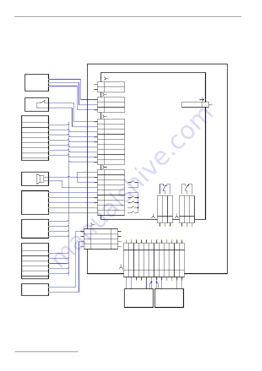
CONNECTION LAYOUT OF THE TB-01 TURNSTILE
AND OPTIONAL EQUIPMENT
3
2
1
8
7
6
5
4
3
2
1
2
2
1
1
33
44
55
66
77
88
99
10
11
12
13
14
C
4
8
1
2
3
4
R0
: D0
R0
: D1
10
11
12
R1
: D1
13
XT5
R1
: D0
14
NO
NC
X1
.2
R0
: Le
d R
ed
R0
: Le
d G
re
en
R0
: Be
ep
er
G
N
D &
Sh
ie
ld
G
N
D &
Sh
ie
ld
R1
: Be
ep
er
R1
: Le
d G
re
en
R1
: Le
d R
ed
Li
gh
t B
8
7
6
5
4
3
2
1
2
2
1
1
XT3
C
+12V
-
+
A7*
A5*
Det Out
Ready
PASS B
+12V
Common
Alarm 2
Alarm 1
GND
XT1.H
XT1.L
GND
+12V
In
XT4
ACS
NC
A6.4*
X1
A2*
A3*
A4
PASS A
XT2
Li
gh
t A
2
3
2
3
button 2
GND
+12VDC
TPS
button 1
yellow
blue
red
common
WRC
black
ACS outputs
turnstile
control
signals on
passage
A6.1*
right button
left indicator
stop indicator
green
yellow
orange
RC
left button
common
black
white
intrusion
detector
ACS
A6.3*
GND
GND
+12V
X1.1
NO
7
8
9
3
4
5
Out
Led B
Led Stop
9
1
Stop
Led A
Unlock B
Unlock A
5
6
7
GND
GND
Fire Alarm
1
2
3
+12V
Detector
1
2
3
1
2
CLB
Control
A1
A8*
button 3
white
A6.2*
right indicator
red
ACS inputs
stop button
blue
+12V
С
onnection
of a Reader
№
1
1
6
2
8
Detector
4
1
TB-01 turnstile
С
onnection
of a Reader
№
2
Figure
А
.1 – Connection layout of the TB-01 turnstile and optional equipment
*
Elements of the scheme are listed in Table A.1.
Summary of Contents for Turnichetul TB 1
Page 37: ...www percoweb com...


