WHD-16 Full Height
Security Gate
11
For installation of the gate together with the
RTD-16
full height rotor turnstiles and the
MB-16
full height railings we recommend he following installation sequence:
1. the turnstile foundation frame;
2. the turnstile;
3. the gate;
4. standard sections of the full height railing;
5. extension sections of the full height railing;
6. the turnstile protective canopy.
Contact
PERCo
Technical Support Department if you need further consulting.
8.4 Installation of the gate
Further in this section each installation operation is described in compliance with the
above guidelines (sect. 8.1).
Recommendations on how to prepare mounting holes in the foundation (the mounting
surface) are given with regard to anchor bolts for solid concrete floors or similar
foundations (sect. 4.2).
1. Unpack the gate; check the delivery set against section 4 of the Manual.
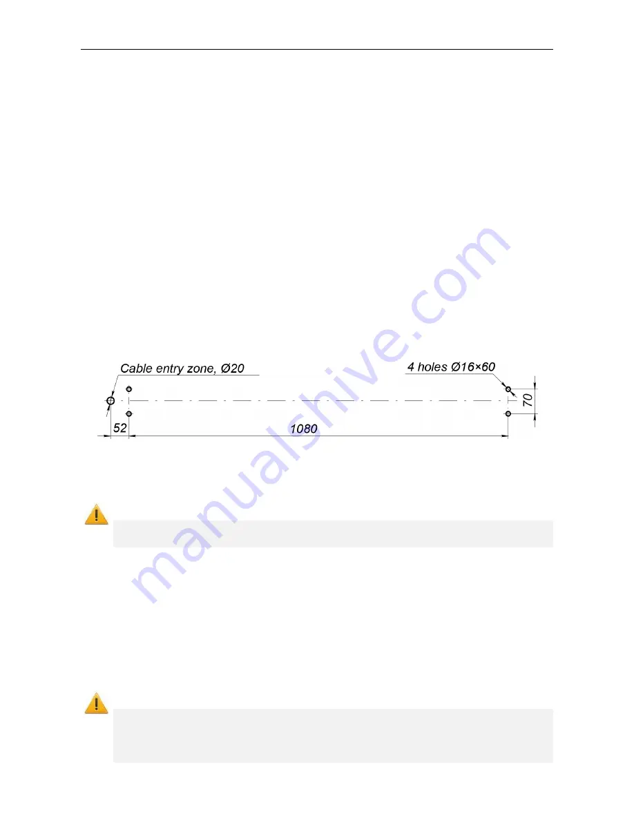
2. Mark out mounting holes and cable ducts. Through cable ducts lay necessary power
cable to the electromagnetic lock (and also if necessary, cable to the door sensor)
(Fig. 3).
Figure 3. Mounting hole pattern
3. Insert sleeves for anchor bolts into the holes so that they do not stick out above the floor
surface.
Attention!
Be extra cautious and careful when carrying out further work . Prevent the gate from
falling.
4. Mount the gate so that the flanges are on their respective mounting holes, fix the gate
with the anchors observing verticality with a level gauge and using joint liners when
necessary.
5. Install the door closer on the mounting holes in the frame and the leaf. If necessary,
adjust the leaf closing speed with the speed-adjusting screws
(see installation and
operation instructions for the door closer).
6. When using a gate in the ACS, connect the power supply and ACS-controller to the
electromechanical lock of the gate (see Figure 4). It is recommended to use a power
supply with a voltage of 12V / 3A (DC or AC).
Attention!
The duration of the control signal from the ACS-controller must be at least 0.5, but
not more than 1 second. A longer control signal can cause the lock malfunction. To
reduce the probability of lock failure, it is recommended to limiting the current in the
power supply circuit of the lock
– install a resistor R1 (12 Ohm / 10 W, Figure 4).
Summary of Contents for WHD-16
Page 1: ...INSTALLATION AND OPERATION MANUAL WHD 16 Full Height Security Gate...
Page 2: ...Full Height Security Gate WHD 16 Installation and Operation Manual...
Page 8: ...WHD 16 Full Height Security Gate 7 Figure 2 Overall dimensions of the WHD 16 gate...
Page 16: ......
Page 18: ...www perco com...


