background image

3

IDENTIFICATION OF PARTS

ACCESSORIES

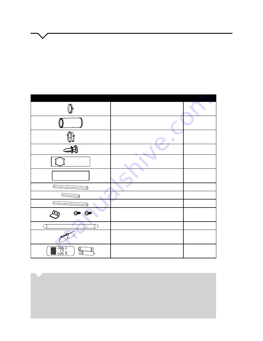
Check that all the accessories are included in the package (Fig. 1) and refer to the installation instructions for their usage. 

Your Window Installation Kit fits windows 26.5 – 48 inches (67.5 – 123 cm) and can be shortened for smaller windows.

TOOLS NEEDED:

  •  Medium Phillips screwdriver

  •  Tape measure or ruler

  •  Knife or scissors

  •  Saw (optional, to shorten window adapter for narrow windows) 

PART

DESCRIPTION

QUANTITY

Unit Adapter

1 pc

Exhaust Hose

1 pc

Window slider Adapter

1 pc

Bolt

1 pc

Window Slider A

1 pc

Window Slider B

1 pc

Foam Seal A (Adhesive)

2 pcs

Foam Seal B (Adhesive)

2 pcs

Foam Seal C (Non-Adhesive)

1 pc

Security Bracket and 2 Screws

1 set

Drain Hose

1 pc

Power Cord Buckle

1 pc

O

N

/O

FF

TE

M

P

SH

O

RT


CU

T

TI

M

ER

  O

N

TI

M

ER

  O

FF

M

O

DE

FA

N

SL

EE

P

SW

IN

G

LE

D

Remote Control and Batteries

1 set

NOTE:

 All of the illustrations in this manual are for explanation purposes only. Your air conditioner may be slightly different.

FIG. 1

 ABOUT FLUORINATED GASES

•  This air conditioning unit is a hermetically sealed unit that contains fluorinated gases. For specific 

information on the type of gas and the amount, please refer to the relevant label on the unit itself.

•  Installation, service, maintenance and repair of this unit must be performed by a certified technician.
•  Product uninstallation and recycling must be performed by a certified technician.
•  When the unit is checked for leaks, proper record-keeping of all checks is strongly recommended.

Summary of Contents for PORTQ12000

Page 1: ...PORTABLE AIR CONDITIONER FOR MODEL PORTQ12000 Before using your air conditioner please read this manual carefully and keep it for future reference along with your receipt USER MANUAL...

Page 2: ...___________________________ Purchase Date _____________________________________ Store Purchased ______________________________________ Installation Date ____________________________________ Installati...

Page 3: ...listed in the accessories chart of this Instruction Manual ENERGY SAVING TIPS Use the unit in the recommended room size Locate the unit where furniture cannot obstruct the air flow Keep blinds curtai...

Page 4: ...replacement work should be performed by authorized personnel only Installation and repair work must be performed in accordance with the national wiring standards by authorized personnel only DO NOT op...

Page 5: ...be pulled into water or any other liquid If the unit does ever fall into water unplug it immediately DO NOT install the unit in a location that may be exposed to combustible gas or other flammable li...

Page 6: ...c Security Bracket and 2 Screws 1 set Drain Hose 1 pc Power Cord Buckle 1 pc ON OFF TEMP S HO R T C U T T IME R O N T IME R O F F MO DE FAN S L E E P S W ING L E D Remote Control and Batteries 1 set N...

Page 7: ...e following 1 Plug in the air conditioner 2 The power supply cord will have TWO buttons on the plug head Press the TEST button The RESET button will click as it pops out 3 Press the RESET button again...

Page 8: ...for you to improvise or modify some aspects of the installation procedures for certain types of windows Please refer to Fig 6 and Fig 7 for minimum and maximum window openings Window slider kit length...

Page 9: ...t of the exhaust hose 20 inch clearance in order to ensure the exhaust system works properly Fig 12 Once the Exhaust Hose assembly and Adjustable Window Slider are prepared choose from one of the foll...

Page 10: ...he glass and the window frame to prevent air and insects from getting into the room STEP 4 Fig 16 If desired install the security bracket with 2 screws as shown STEP 5 Fig 17 Insert the window slider...

Page 11: ...the glass and the window frame to prevent air and insects from getting into the room STEP 4 Fig 21 If desired install the security bracket with 2 screws as shown STEP 5 Fig 22 Insert the window slider...

Page 12: ...so there are no leaks Direct the hose toward a floor drain making sure that there are no kinks that will stop the water flow Place the end of the hose into a drain and make sure the end of the hose is...

Page 13: ...the hose directly over the drain area in your basement floor or over a shallow pan if no floor drain is available See Fig 23 24 Remove the plug from the bottom drain outlet the water in the bottom tra...

Page 14: ...y settings in a range of 35 RH Relative Humidity to 85 RH in 5 increments only for models with humidity sensor NOTE The control is capable of displaying the temperature in degrees Fahrenheit or degree...

Page 15: ...es until the FOLLOW ME button is pressed again If the unit does not receive the Follow Me signal during any 7 minute interval the unit will beep to indicate use of the Follow Me feature has ended The...

Page 16: ...uto timer settings ad the humidity settings for models with humidity sensor only when on DRY and FAN modes it shows the room temperature It also shows the following Error and Protection Codes ERROR AN...

Page 17: ...filter Refer to Care and Cleaning section To defrost set to FAN only mode Thermostat is set too cold for night time cooling To defrost the coil set to FAN only mode Then set temperature to a higher se...

Page 18: ......

Page 19: ......

Page 20: ...Perfect Aire LLC 5401 Dansher Rd Countryside IL 60525 844 4PA AIRE 844 472 2473 www perfectaire us Specification and performance data is subject to change without notice Printed in China PA User_PORTQ...

Reviews: