background image

A8

-W5

assembly parts list 5

Summary of Contents for A8-W5

Page 1: ...A8 W53DPrinterInstallationGuide Perfect Office ...

Page 2: ...he package not broken when you receive it 2 Pleasechecktheprinterpartsaccording tothepackinglist 3 Please contract your supplier if any questions 4 The installation of graphics and text for the model diagram for reference only in kind to receive goods prevail ...

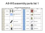
Page 3: ...A8 W5 assembly parts list 1 ...

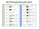
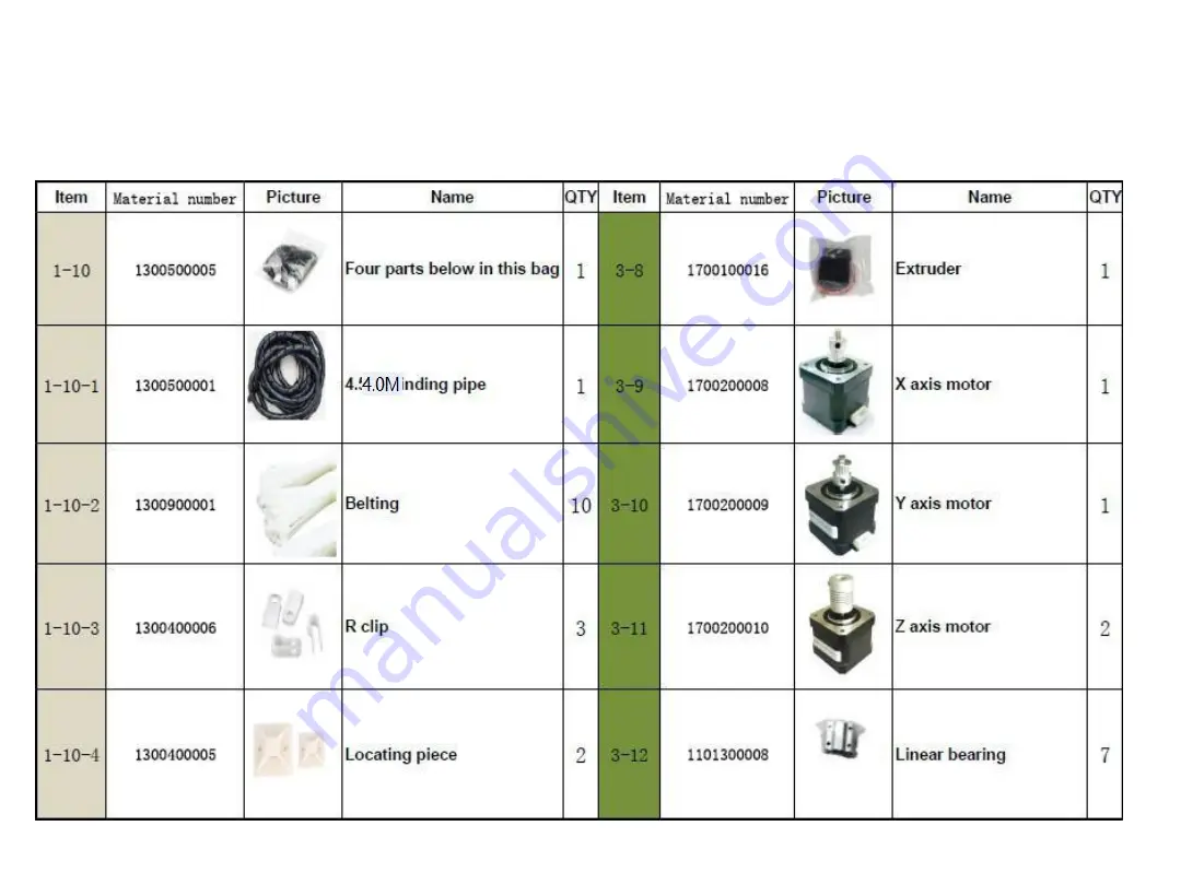
Page 4: ...A8 W5 assembly parts list 2 ...

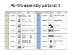
Page 5: ...A8 W5 assembly parts list 3 ...

Page 6: ...A8 W5 assembly parts list 4 ...

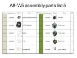
Page 7: ...A8 W5 assembly parts list 5 ...

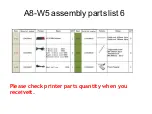
Page 8: ...A8 W5 assembly parts list 6 Please check printer parts quantity when you receiveit ...

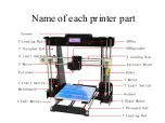
Page 9: ...Name of each printer part ...

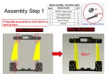
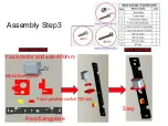
Page 10: ...Step1 Assembly Step1 Pleasebeawarethescrewholesisin red circles ...

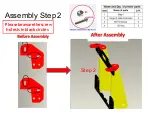
Page 11: ...Assembly Step2 Pleasebeawarethescrew holesisinblackcircles Step 2 ...

Page 12: ...Assembly Step 3 Yaxis motorand wire 400mm Motorfixingplate Yaxispositionswitch700mm Rearfixingplate Step ...

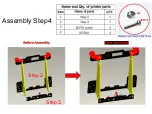
Page 13: ...Assembly Step4 Step 2 Step 3 ...

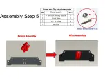
Page 14: ...Assembly Step5 ...

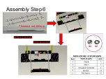
Page 15: ...Assembly Step6 Threaded rod 400mm ...

Page 16: ...YGuiderod380mm Assembly Step7 ...

Page 17: ...Attention Leave vacancy between belt fixation clampandhotbedfixedplateforbeltpositioning Assembly Step8 ...

Page 18: ...Assembly Step9 Before Assembly After Assembly Attention Pleasediagonallytightenthescrewswhen allareinthereplace ...

Page 19: ...Assembly Step10 Attention Belt is for X Y axis transmitting Cut the length you need toeach transmission shaft The belt is 1 5 mintotaland 10 20cm left after installation ...

Page 20: ...Assembly Step11 Wing nut swill keep the height of hot bed levelas well as firming the hot bed Attention Hotbed screws should be in the bottom ...

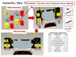
Page 21: ...Assembly Step 12 Attention This hole is for Z axis guide rod po sitioning ...

Page 22: ......

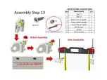
Page 23: ...Assembly Step14 ...

Page 24: ...Assembly Step15 T lead screw 345mm Attention loose the jackscrew of elastic coupling to place T lead screw tothe bottom thentighten ...

Page 25: ...p 16 X axis Guide rod 436mm After installation tighten the top wire at the back Attention Please keepA Batthesameleveldurin g X rods installation Knock the guide rods with a hammer slightly if it s hard toplace 已审批 ...

Page 26: ...Assembly Step17 Beforedisassembly After disassembly LooseM4 6 screws first thenseparate extruder from L black aluminum parts rememberto After disassembly ...

Page 27: ...Assembly Step18 M3 45screwholes Replace M3 20 screwswithM3 45 screws ...

Page 28: ...Assembly Step 19 ...

Page 29: ...Assembly Step20 Attention Install M4 6 screw Tighten M6 Screw on the throat with spanner till extruder is not loose ...

Page 30: ...Assembly Step 21 ...

Page 31: ...AssemblyStep22 M3 20 ...

Page 32: ...AssemblyStep 23 Attention Belt is for X Y axis transmitting The length of belt is 1 5m in total Normally there ll be 10 20cm left after installation ...

Page 33: ...Assembly Step24 M3 Nut ...

Page 34: ...Assembly Step25 ...

Page 35: ...iring diagram of power supply 1 2 3 seperately represent the line offire brown Zero line blue ground wire yellow 4 5 6 represent negative pole black 7 8 9represent the positive pole red Toavoid danger please assure the installation is correct ...

Page 36: ...Assembly Step27 Redcirclesstandfor thepower screw holes PowerSupply ...

Page 37: ...Assembly Step28 Mainboard ...

Page 38: ...Attention Please use the corresponding wire especially motor wire limited switch wire Assembly Step29 ...

Page 39: ...Assembly Step30 Attention Please connect the electronics wire to each components correspondingly ...

Page 40: ......

Page 41: ...AssemblyStep 32 InstallationPicture1 ...

Page 42: ...AssemblyStep 32InstallationPicture 2 ...

Page 43: ...ion Complete Congratulations Youhavejustmadeyourselfa3D printer Please contact your 3D printer supplier if any puzzlesduringusing process Thank you for choosing our products we will alwaysprovideyoumoreservices ...

Reviews: