background image

PARTS DRAWING

3

1

4

6

7

8

9

11

10

12

13 14 15

18

23

24

25

26

27

28

29

30

36

37

38

39

40

2

5

31

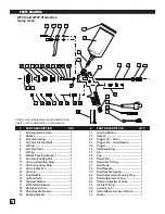
M706 and M707 Production
Spray Guns

32

33

34

35

16

17

19 20

21

22

6

Please note: Replacement parts listed below
apply to all models listed on this manual.

Air Adjustment Valve ......................... 1 

21 

Locking Spring ................................. 1

Gasket ............................................... 1 

22 

Gasket ............................................... 1

Air Valve Spring ................................. 1 

23 

Trigger Pin - Pivot ............................. 1

Air Valve Piston Shaft ....................... 1 

24 

Trigger Pin - Fluid Needle ................ 1

O-Ring ............................................... 1

25 

Trigger ............................................... 1

Air Valve Seat .................................... 1 

26 

Retaining Ring .................................. 2

O-Ring ............................................... 1

27 

Lid ..................................................... 1

Pliable Packing Washer .................... 1 

28 

Cup ................................................... 1

Air Valve Packing Nut ....................... 1 

29 

Fluid Filter ......................................... 1

10  Air Cap Retention Ring ..................... 1 

30 

Fluid Inlet Fitting ............................... 1

11  Air Cap Locking Ring ........................ 1 

31 

Gun Body .......................................... 1

12  Air Cap Washer ................................. 1 

32 

Fluid Needle...................................... 1

13  Air Cap ............................................... 1 

33 

Fluid Needle Spring .......................... 1

14  Fluid Nozzle ....................................... 1 

34 

Fluid Adjustment Locking Ring ....... 1

15  Air Manifold ....................................... 1 

35 

Fluid Adjustment Knob .................... 1

16  Tapered Washer ................................ 1 

36 

Pattern Adjustment Valve ................ 1

17  Air Manifold Spacer .......................... 1 

37 

Air Inlet Fitting .................................. 1

18  Retention Screw................................ 1 

38 

Gun Wrench ...................................... 1

19  Paint Needle Washer ........................ 1 

39 

Internal/External Hex Wrench .......... 1

20  Sealing Washer ................................. 1 

40 

Brush................................................. 1

PART DESCRIPTION 

QTY .

PART DESCRIPTION 

QTY .

Spray Gun Rebuild Kit

Numbers in black indicate parts

included in Spray Gun Rebuild Kit.

Summary of Contents for M706

Page 1: ...Gravity Feed HVLP Spray Gun OWNER S MANUAL Stock Numbers M706 M707 FOR YOUR SAFETY please read these instructions carefully and retain them for future use ...

Page 2: ...Table of Contents Specifications 3 Important Safety Information 3 Maintenance Inspection 4 Operating Instructions 4 5 Parts Breakdown 6 Troubleshooting Chart 7 Warranty Information 8 2 CONTENTS ...

Page 3: ...terial check with your supplier Do not use acids for cleaning Always keep work area free from obstructions and well ventilated Always disconnect spray gun from air source before disassembly SPECIFICATIONS IMPORTANT SAFETY INFORMATION 3 WARNING Failure to heed these warnings may result in personal injury or property damage Specifications are subject to change without notice Operating Pressure 15 45...

Page 4: ...s are tight with no leaks Replace any worn parts as necessary Check needle and nozzles for nicks scratches or burrs Any such conditions will seriously impair performance Replace as necessary OPERATION 4 STEP 1 Inlet Air Pressure Regulation Assemble components of spray gun and connect to clean air source as described above Set inlet air pressure to between 20 and 30 P S I to begin adjustments This ...

Page 5: ...set you can lock the adjustment by turning the lock nut in tight Spray Pattern Control Pattern Shape The shape of the spray can be adjusted from a round pattern to a flat pattern by turning the Pattern Control Knob Turning knob in rounds the pattern turning knob out flattens the pattern Pattern Orientation A flat or semi round spray pattern can be adjusted to any angle from horizontal to vertical ...

Page 6: ...t 1 26 Retaining Ring 2 7 O Ring 1 27 Lid 1 8 Pliable Packing Washer 1 28 Cup 1 9 Air Valve Packing Nut 1 29 Fluid Filter 1 10 Air Cap Retention Ring 1 30 Fluid Inlet Fitting 1 11 Air Cap Locking Ring 1 31 Gun Body 1 12 Air Cap Washer 1 32 Fluid Needle 1 13 Air Cap 1 33 Fluid Needle Spring 1 14 Fluid Nozzle 1 34 Fluid Adjustment Locking Ring 1 15 Air Manifold 1 35 Fluid Adjustment Knob 1 16 Tapere...

Page 7: ...on the Air Nozzle ears Irregular or Offset Pattern This can be caused by 1 A dirty or damaged Needle tip or Fluid Nozzle 2 Clogged atomization holes on Air Nozzle around the center Spitting 1 Too little material in cup 2 Loose Fluid Nozzle 3 Damaged Needle Packing 4 Dirty or damaged Needle Nozzle Set Material in cup bubbles or Boils 1 Loose clogged or damaged Fluid Nozzle 2 Loose clogged or damage...

Page 8: ...ducts Except for warranties of title and the limited express warranties set forth above Performance Tool makes no express or implied warranties of any kind with respect to its products In particular Performance Tool makes no implied warranty of merchantability and no implied warranty of fitness for any particular purpose except that for goods purchased primarily for personal family or household us...

Reviews: