4
9
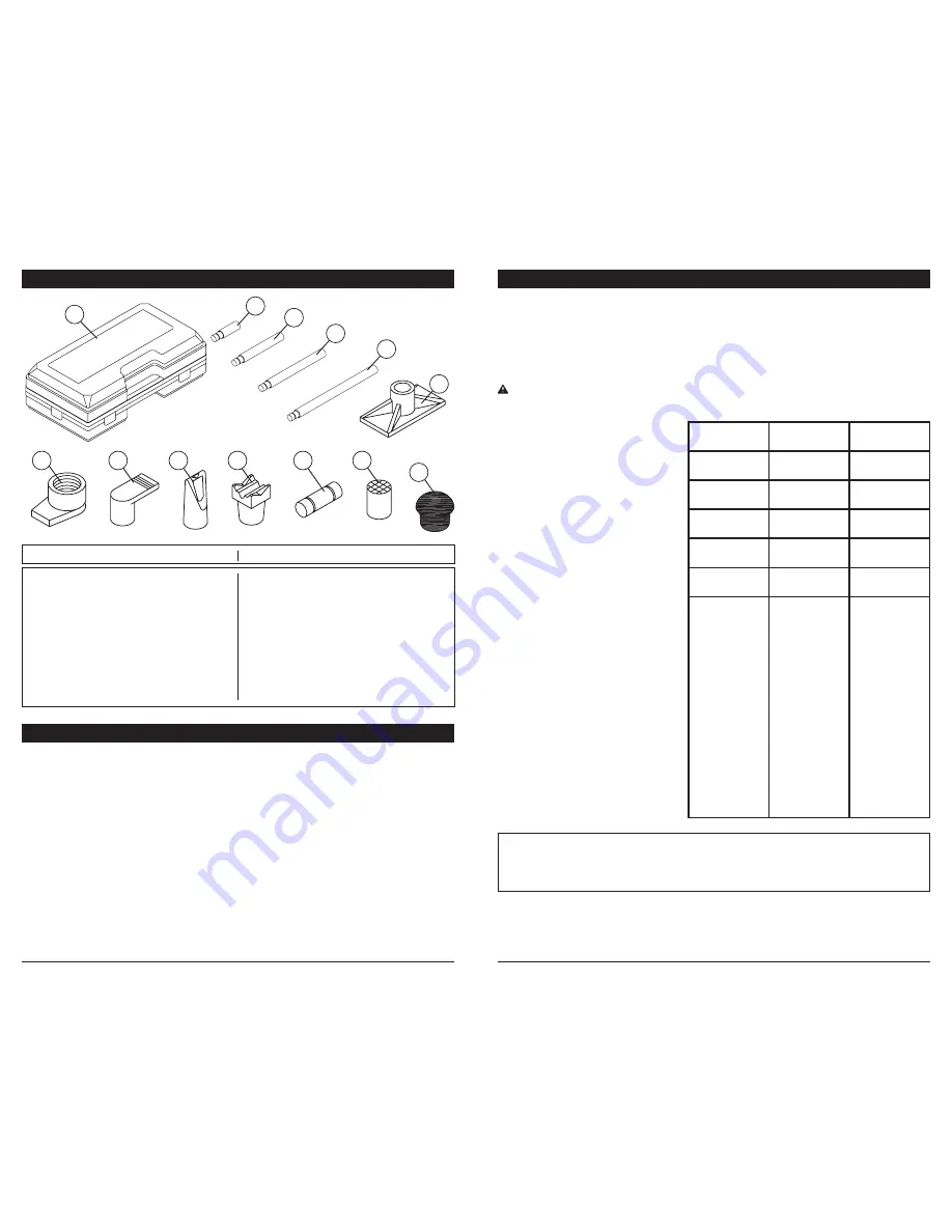
Ram Attachments:
1. The Extensions (5-8) connect in different
combinations to reach desired lengths.
2. The Male Connector (14) is used to con-
nect the female end of the Ram (3) to a
Base.
3. The Flat Base (9) is typically used on the
stationary side to spread out the force of
the Ram (3).
4. The V-Base (13) is used to offset the
force of the Ram (3) when there is not a
straight line between the stationary side
and the damaged side, or to spread out
force on curved surfaces.
SETUP INSTRUCTIONS
PACKAGING CONTENTS
1
Pump
1
2
Spreader Wedge
1
3
Ram
1
4
Case
1
5
3 3/4 in. Extension
1
6
5 in. Extension
1
7
8 1/2 in. Extension
1
8
16 1/2 in. Extension
1
9
Flat Base
1
10
Ram Toe
1
11
Plunger toe
1
12
Wedge head
1
13
V-base
1
14
Male Connector
1
15
Cap Head
1
16
Rubber head
1
#
Description
Quantity
#
Description
Quantity
4
5
6
7
10
12
13
8
9
14
15
16
11
5. The Cap Head (15) is typically used on
the pushing end to prevent slipping.
6. The Rubber Head (16) is typically used
for popping dents out of sheet metal such
as doors or body panels and to minimize
damage to the work surface.
7. The Wedge Head (12) is used to repair
small dents and areas located in angles
and tight spaces.
8. The Ram Toe (10) and Plunger Toe (11)
are used together to allow spreading in
areas that the Ram cannot fit into.
NOTE:
Problems listed above with more than one solution may have a combination of causes. Please be sure
that all solutions listed for each problem have been checked to eliminate possibility of further trouble.
Sometimes solutions may need to be repeated for best results.
TROUBLESHOOTING
This Performance Tool® product was constructed with quality materials and workmanship
and will give you many years of trouble free use when cared for as described in the "Care
& Maintenance" section on page 7-8. However, as with any mechanical device, periodic
adjustments are necessary to maintain a peak level of performance. Should this product
be displaying any of the following symptoms, the simple procedures shown below will
correct the problem.
WARNING: Remove all equipment from service before making adjustments
●
●
●
●
●
●
●
●
●
●
Power unit may
be low in fluid.
With pump on
level surface and
in down position,
remove filler plug
and add clean
hydraulic jack fluid
to level of filler.
Power unit may
be air bound.
Open the release
valve a minimum
of 2 full turns.
Pump the handle
a minimum of 20
full strokes to
purge air from the
system.
Valve may not be
closing
completely.
To seat valves:
a.) Close release
valve.
b.) With pump in
fully lowered
position,
manually raise
lifting arm as
high as
possible.
c.) Open release
valve and
allow pump to
descend to
lowered
position
Will not lift load
Will not hold load
Will not lift to full height
Pump feels "spongy" under load
Handle raises under load
Handle lowers under load


