background image

36

Application

Hydraulic Head Spindle Device VST

Translation of the Original Instructions for Use

Troubleshooting

Cylinder is extended 
but does not withstand 
the pressure.

Cylinder cannot be ex-
tended, extends too 
slowly, or stops during 
the start-up.

Malfunction

Malfunction

Possible cause

Possible cause

Remedial action

Remedial action

Open drain valve.

Internal leakage in the 
pump.

Loose connection on 
the hydraulic pump.

Load too heavy.

Trapped air in the  
system.

Cylinder piston is stuck.

Leaky connection.

Defective seal.

Drain valve opened.

Oil level is too low in  
the pump.

Top up oil in accordance with the 
Maintenance and Repair section.

Close drain valve.

Arrange to have the pump  
serviced by a qualified hydrau-
lics technician.

Check that all couplers have 
been completely tightened.

Do not try to lift more than the 
nominal load of 700 kN (680 bar).

Bleed air in accordance with the 
instructions provided in the  
Hydraulics section.

Check the cylinder for signs of 
damage. Arrange to have the 
cylinder serviced by a certified 
hydraulics technician.

Check whether all connections 
are tight and leak-proof. If yes, 
depressurize the system.

Locate leakage and then arrange 
to have the connectors and  
couplings serviced by a qualified 
hydraulics technician.

Close drain valve.

EN_BA_Hydr_Kopfspindeleinheit_VST.indb   36

01.04.16   11:25

Summary of Contents for 117465

Page 1: ...Hydraulic Head Spindle Device VST Item no 117465 Item no 117678 Translation of the Original Instructions for Use Edition 02 2016...

Page 2: ...umentation 12 Identification markings 13 Care and maintenance instructions 16 Inspections 18 Technical data 20 Application Commissioning 22 Assembly 26 Height adjustment 29 Lowering 32 Dismantling 34...

Page 3: ...ginal Instructions for Use 1 1 2 4 2 3 2 2 2 1 1 3 1 4 1 5 1 1 2 1 Head Spindle VST 100 1 1 Fork Head 1 2 Centering Jaws 1 3 Spindle Nut 1 4 Spindle Sleeve 1 5 Mounting Shaft VST 2 Hydraulic Unit VST...

Page 4: ...measure e g cm are shown in the illustrations Load details are usually given in kg Other measurement units e g t are shown in the illustrations Conventions Instructions are numbered with 1 2 3 The re...

Page 5: ...if not avoided could result in death or serious injury Warning This sign indicates a hazardous situation which if not avoided could result in death or serious injury Caution This Sign indicates a haz...

Page 6: ...e for obvious defects e g deformations cracks breaks incomplete markings Do not use damaged products Do not use PERI products if the markings are missing or illegible Safety instructions Do not expose...

Page 7: ...ght bends kinks should be avoided Safety instructions During assembly or dismantling of the hydraulic components the system pressure must be 0 bar 0 psi Do not touch pressurized hydraulic hos es Press...

Page 8: ...ice VST are provided in the corresponding Instructions for Assembly and Use of the system The Hydraulic Head Spindle Device VST is not approved for transporting persons Intended use The product descri...

Page 9: ...sk Changes to PERI components are not permitted Only PERI original components may be used The use of other products and spare parts represents a misapplication with associated safety risks Operations...

Page 10: ...ty and health plan coordinates the protective measures for the contractor and site personnel so that they do not endanger each other monitors and ensures compliance with the protective measures Valid...

Page 11: ...measures in order to safely assemble modify or dismantle the scaffolding Designation of the preventive meas ures to avoid the risk of persons and objects falling Designation of the safety precautions...

Page 12: ...aggressive materials if safety is then likely to be affected During transport intermediate storage or when remaining suspended on the load ensure that the product remains free of dirt and that its fu...

Page 13: ...iginal Instructions for Use Fig 1 2 1 2 2 2 3 2 4 2 4a 2 5 2 6 Hydraulic Unit VST 2 1 2 2 2 6 2 5 2 4 2 3 2 4a Hydraulic cylinder 1x Hydraulic hose 1x Manometer 1x Hydraulic hand pump 1x Vent and fill...

Page 14: ...acking Devices Instructions for Assembly and Use VARIOKIT Heavy Duty Shoring Tower VST Brochure Engineering Construction Kit Transportation position 1 Turn the spindle nut 1 3 with mount ing shaft ant...

Page 15: ...on Do not use the Hydraulic Head Spin dle Device VST if the type plate is missing or illegible Do not use the Hydraulic Head Spin dle Device VST if the inspection sticker is missing has expired or is...

Page 16: ...ulic Head Spindle Device VST Translation of the Original Instructions for Use Identification markings Hydraulic Unit VST Max operating pressure 680 bar 700 kN Hydraulic Unit VST Hydraulic hand pump Wa...

Page 17: ...15 Introduction Hydraulic Head Spindle Device VST Translation of the Original Instructions for Use Hydraulic Unit VST Warning sign on hydraulic hose Hydraulic hose...

Page 18: ...arts Clean the Head Spindle VST 100 before and after every use and grease the me chanical components with an appropriate lubricant Long Life Grease LT 200 EP or equivalent Maintenance and repair work...

Page 19: ...ginal Instructions for Use Introduction Fig 7 2 4c 2 4d 2 4e Lubrication of the pump Depending on the application and fre quency the supporting bolts 2 4c the cylinder surface 2 4d and lever arm guide...

Page 20: ...is recommended to proceed according to German rules and regula tions The contractor is responsible for deter mining the type scope and intervals for the required inspections relating to the provision...

Page 21: ...welding seams and components only original PERI components may be used indications of inpermissible heating or contact with fire markings must be legible 4 3 Functional check Free and easy movement o...

Page 22: ...nternal diameter Weight Weight Type Pressure stages Max nominal pressure Oil volume per stroke Usable oil capacity Changeover pressure Max leverage force Piston stroke Weight Description Description L...

Page 23: ...sure Viscosity at 210 F 100 C Stroke Viscosity at 100 F 38 C Overall height retracted Viscosity at 20 F 0 C Max overall height API gravity Effective piston area Flashpoint C O C Oil volume Flow point...

Page 24: ...ec essary Bleed system Bleeding the hydraulics 1 Close drain valve 2 4b by turning in a clockwise direction 2 Position the hand pump at a higher level than the cylinder 3 Bottom of the hydraulic cylin...

Page 25: ...il can lead to a malfunction Procedure 1 Retract hydraulic cylinder 2 1 2 Open the vent and filler cap 2 4a on the oil tank of the hand pump 2 4 3 Tip the hand pump 4 Put used oil in a suitable contai...

Page 26: ...raulic oil Completely retract the hydraulic cylin der Too much oil can lead to a malfunction Procedure 1 Open the vent and filler cap 2 4a on the oil tank of the hand pump 2 4 2 Check the oil level by...

Page 27: ...25 Hydraulic Head Spindle Device VST Translation of the Original Instructions for Use...

Page 28: ...dure 1 Loosen the four bolts of the fork head 1 1 by turning them counter clock wise and then remove Fig 11 2 Remove spacer plates 1 6 and adjust centering jaws 1 2 by moving to width x of the crossbe...

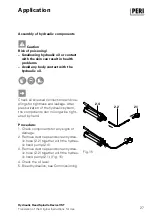
Page 29: ...ck all screwed connections and cou plings for tightness and leakage After pressurization of the hydraulic system the components can no longer be tight ened by hand Procedure 1 Check components for any...

Page 30: ...shoring system has been completely assembled Follow Instructions for Assembly and Use for the PERI Heavy Duty Shoring Tower VST Procedure 1 Position hydraulic cylinder 2 1 in the Head Spindle VST 100...

Page 31: ...ht When working on existing struc tures permanently monitor the situ ation e g cracks falling building parts or noises If the specified height has been reached secure with the spindle 1 3 nut in order...

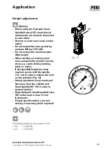
Page 32: ...t adjustment Warning Take into consideration max spin dling height Thread must be visible in the inspection holes Raise the Head Spindle VST 100 in maximum 10 mm increments As long as the thread is vi...

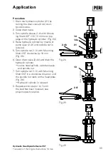
Page 33: ...leeve rests on hydraulic cylinder Fig 21 5 Raise hydraulic cylinder max 10 mm with the pump handle 2 4f Fig 22 g gRaise Head Spindle and spindle sleeve 6 Turn spindle nut 1 3 with Mounting Shaft VST i...

Page 34: ...o During operations keep hands and feet away from the cylinder and Head Spindle VST 100 in order to prevent injuries With a multiple number of spindles ensure that all spindles are lowered uniformly D...

Page 35: ...lic cylinder by means of pump lever 2 4f until spindle nut is relieved 5 Turn spindle nut 1 3 with Mounting Shaft VST clockwise by 10 mm Fig 25 6 Open drain valve 2 4b and drain the hydraulic cylinder...

Page 36: ...drain valve 2 4b g gHydraulic cylinder retracts 2 1 g gSystem is pressureless 2 Close drain valve by turning in a clockwise direction 3 Remove hydraulic cylinder from the Head Spindle VST Fig 28 4 Un...

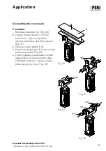
Page 37: ...the four bolts 1 7 of the fork head 1 1 by turning them counter clockwise and then remove Fig 31 3 Remove spacer plates 1 6 4 Extend centering jaws 1 2 by moving as far as possible Fig 32 5 Position...

Page 38: ...opened Oil level is too low in the pump Top up oil in accordance with the Maintenance and Repair section Close drain valve Arrange to have the pump serviced by a qualified hydrau lics technician Chec...

Page 39: ...ssage in the hose restricts oil flow Internal cylinder damage Trapped air in the system Drain valve closed Remove air bleed in accordance with the instructions provided in the Hydraulics section Open...

Page 40: ...uctions for Use Disposal Disposal of the Hydraulic Head Spindle Device VST must be arranged by an au thorized person Caution Separate materials correctly and according to type The materials are to be...

Page 41: ...kg Head Spindle VST 100 As head spindle for the VARI OKIT Heavy Duty Shoring Tower As an option can be used with the hydraulic de vice Hydraulic Unit VST Flexible hydraulic unit for use in the Head S...

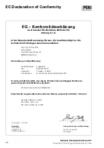
Page 42: ...olz PERI GmbH Rudolf Diesel Stra e 19 89259 Wei enhorn Beschreibung und Identifizierung Produktgruppe Typ Artikel Nr Handels Bez Tragger st Absenkeinheit 117465 117678 Hydraulische Kopfspindeleinheit...

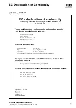
Page 43: ...Ing Rainer Bolz PERI GmbH Rudolf Diesel Strasse 19 89259 Weissenhorn Product Group Typ Article No Commercial Designation Description and identification European Directive On Machinery 2006 42 EC It i...

Page 44: ...42...

Page 45: ...43...

Page 46: ...peri com System Independent Accessories Column Formwork Wall Formwork Slab Formwork Climbing Systems Bridge Formwork Tunnel Formwork Shoring Systems Construction Scaffold Industrial Scaffold Facade Sc...

Reviews: