For the customer use only
Pericom Semiconductor Corp.
www.pericom.com
Page 5 of 8
9/3/2010
AN
05/05/04
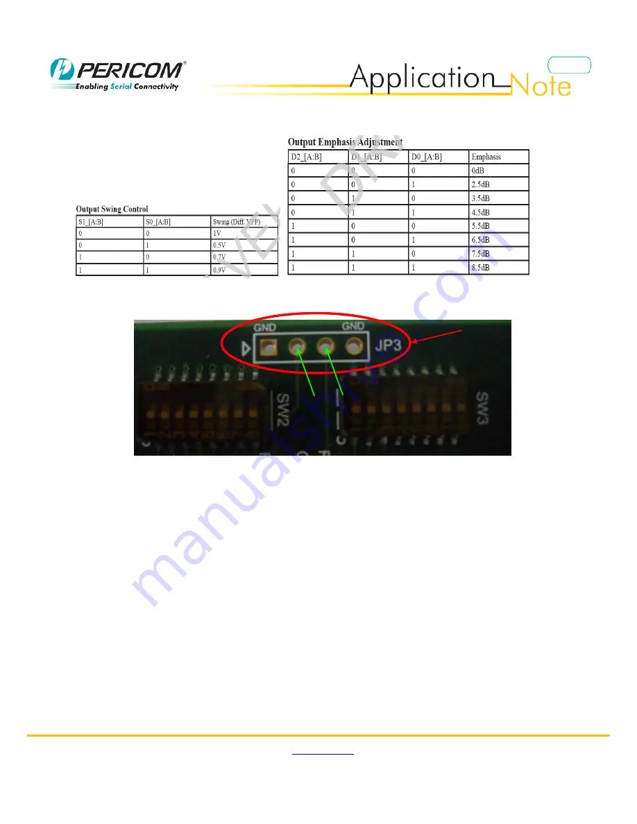
Figure7 shows output configuration table for Channel A and B.
Figure6 Output Configuration Table for Channel A and B
For detail I2C configuration function please refer to Page7-13 on the datasheet. There is one connector-
JP3
as
Figure7 on the demo board for I2C connection.
Figure7 JP7 location for I2C connection
Also there are three LED lights for power supply, signal detect output for Channel A and B.
D1
: signal detect output for Channel A, not available
D2
: signal detect output for Channel B, not available
D5: Power supply
JP3 location
SCL
SDA


