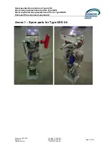
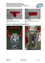
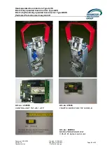
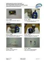
Hand-operated boom barriers Type GHS
Electrically operated boom barriers Type GES
Electro-hydraulically operated boom barrier Type GEHS
P
erimeter
P
rotection
G
ermany
G
mbH
Document: 2050274
Created: 11.04.2011
Version: a
Changed: 15.08.2013
Page 88 of 93
Original version
Subject to change
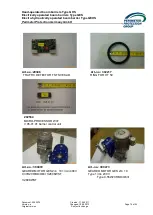
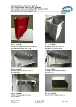
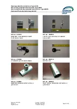
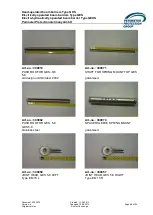
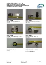
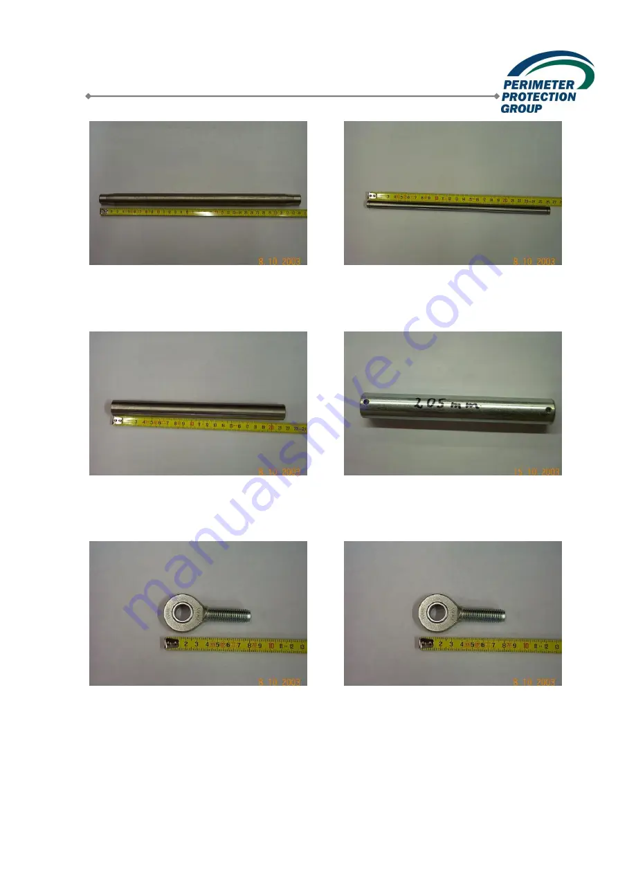
Art.-no.: 300910
Art.-no.: 300971
PUSH ROD FOR GES.-5/6
SHAFT FOR SPRING MOUNT TOP GES
5-8
old design until October 2002
galvanised
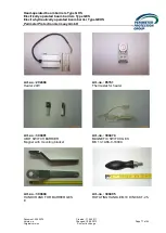
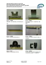
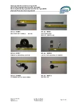
Art.-no.: 300962
Art.-no.: 300974
PUSH ROD FOR GES. 5-8
SPACER SLEEVE SPRING MOUNT
GES 5-8
stainless steel
galvanised
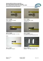
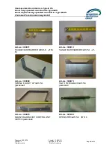
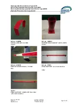
Art.-no.: 300958
Art.-no.: 300957
JOINT HEAD, GES 5-8 LEFT
JOINT HEAD, GES 5-8 RIGHT
Type EM 15 L
Type EM 15 R


