background image

2

ADVANCED FUNCTION WITH LIVEVIEW

4. ADVANCED FUNCTION WITH LIVEVIEW

4.1                     Image direction control: Up/Down/Left/Right/Home

4.2                    Image zoom IN/OUT, 15 Level.

4.3                      Automatic Left/Right Pan

4.4                       Night LED On/Off Button

4.5                                    Manual Record Button

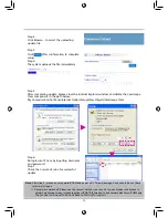
Step 1: 

Move the cursor below the Record, a "click 

to enable and use this control" message will 

appear. Click it with left mouse button to 

enable this function (as shown below).

Step 2: 

Click "start" once to access next page (as shown 

below).

Step 3: 

Period(min) is used to set recording 

time. Unselect the Enable for continuous 

recording. Path is for assigning path to 

save recorded video file, folder can also 

be use to select path.
Step 4: 

Click Start to Record button to return to 

Lifeview screen and start recording. "REC" 

shows up on the upper left corner. To 

stop recording, please click stop button.

4.6

4.6.1                                               You can set at Fast, Normal and Slow.

4.6.2                                               You can choose from 640*480, 320*240 and 176*144.

4.6.3                                               You can choose from Fixed and Night.

(Note: Fixed: Night vision illumination unchanged;  Night: Night vision illumination Increased)

4.6.4                                                You can choose from 50Hz and 60Hz.

Summary of Contents for PERICAM-902

Page 1: ...IP Surveillance Camera Wireless Pan Tilt Remote Control Night Vision User s Guide Wireless Pan Tilt FCC ID RUJ LR802UWG PERICAM 902 ...

Page 2: ......

Page 3: ...5 IP CAM NETWORK FRAMEWORK INSTALLATION 12 2 6 INSTALLATION FOR IP SHARE 19 2 7 INSTALLATION FOR WIRELESS IP SHARE 21 3 GETTING STARTED 3 1 SYSTEM LOGIN 24 3 2 LIVEVIEW 25 3 3 TAKE A SHOT 26 4 ADVANCED FUNCTION WITH LIVEVIEW 27 5 ADVANCED APPLICATION 5 1 IMAGE CONTROL 28 5 2 LAN SETUP 30 5 3 WLAN SETUP 31 5 4 NETWORK STATUS 32 5 5 SYSTEM LOG 33 5 6 ADMIN SETUP 33 5 7 PPPOE PPPOE 35 5 8 DYNAMIC DNS...

Page 4: ...he device and trigger to sending images to FTP E Mail PC Support virtual IP and port switch in IP share Support several communication protocols TCP IP DHCP SMTP FTP PPPoE DDNS Use functional authority setting name registration and password protection Support the dynamic IP network function of DHCP Support ADSL network of PPPoE user Standard RJ 45 network connector support 10 100 BaseT network tran...

Page 5: ...er s Guide 7 Accessory for hanging and fastening 1 5 SYSTEM REQUIREMENT PC Processor Intel Pentium 4 1 4GHz or above is recommended RAM 256MB or above Operation System Windows 2000 or Windows XP Hard Disk Minimum 100MB or above Read only CD ROM for IPCamFinder installation Network Network Card 10 100 baseT TX Fast Ethernet Wireless Network I EEE 802 11 b g or higher Network Setup Accessing Interne...

Page 6: ...tory default settings Power On description After inserting the included 5V 1 5A Switching Power adaptor into power outlet you have to wait for 40 seconds of power on time for IP Cam to confirm its software hardware are normal The Status Light will light up and execute the motor homing action once power is on 1 7 PRODUCT SET UP IR LED X 6 Focus Adjustable Status Light DC JACK Antenna RJ 45 JACK Anc...

Page 7: ...nge program code update strongly recommended The operation steps are listed below A Installing the Product for the first time Your computer must be equipped with network card and RJ 45 network connector Connect the RJ 45 terminator on the rear of IP CAM with the red test network cable One end is connected to the network card of computer the other end is connected to the rear side of the IP CAM Con...

Page 8: ...r mouse select Properties P Select Internet Protocol TCP IP Select Properties R then you can check the current IP address status for the computer The way to modify IP address is D Open and execute IPCamFinder as shown in Figure 2 The system will automatically scan the IP CAM that you just installed Then you will find 00 15 0F 00 00 22 192 168 1 100 in the column of IP Cam List Click 00 15 0F 00 00...

Page 9: ...AM Detailed information is listed as 2 4 1 2 4 3 2 4 SETTING THE WAY TO OBTAIN THE IP ADDRESS OF IP CAM 2 4 1 STATIC IP Address Setting Your computer must be equipped with network card and RJ 45 network connector Connect the RJ 45 terminator on the rear of IP CAM to the red test network cable One end is connected to the network card of computer the other end is connected to the rear side of the IP...

Page 10: ...26 1039 Step 7 After finishing the settings click Setting to send The network settings for this IP CAM are renewed 4 5 6 7 Figure 3 Example 1 Set up the IP CAM with fixed IP address 2 Turn on your computer and open IE browser Type 211 78 174 94 1025 1026 1039 in the Address line Now you can access into the monitoring screen of network 2 4 2 DHCP IP Address Setting Use RJ 45 Ethernet cable red to c...

Page 11: ...0 Step 3 Click 00 15 0F 00 00 22 192 168 1 100 with left mouse button Open and execute IPCamFinder as shown in Figure 5 Press Update to automatically scan the IP CAM that you just installed Then you will find 00 15 0F 00 00 22 192 168 1 100 in the column of IP Cam List Click 00 15 0F 00 00 22 with left mouse button You can see the default settings for IP CAM Figure 5 1 2 3 Change the default Manua...

Page 12: ...d You will find a 00 15 0F 00 00 22 192 168 1 100 camera in the IP Cam List column Click 00 15 0F 00 00 22 with left mouse button once and the IP CAM default values are filled into the lower columns After changing the connection mode to PPPoE and filling in User Name and Password click the Setting button again A new set of IP Address 00 15 0F 00 00 22 125 225 2 202 appears in the upper search colu...

Page 13: ...word click the Setting button again A new set of IP Address 00 15 0F 00 00 22 125 225 2 202 appears in the upper search column Click 00 15 0F 00 00 22 again to fill the new Address data into the following columns Step 5 Click Show IP Cam with left mouse button once to automatically open Browser and access into network monitoring screen Example 1 Now IP CAM is set up with the IP address in LAN 2 Or...

Page 14: ...o the red test network cable One end is connected to the network card of computer the other end is connected to the rear side of the IP CAM 2 Refer to 2 4 1 STATIC IP Address Settings to type the IP address properly 3 Set a physical IP address for each IP CAM 4 Set up the IP CAM with fixed IP address 5 For viewing images in IP CAM from remote computer Open IE browser and type in the physical IP ad...

Page 15: ... the IP configuration for each IP CAM please assign different virtual IP address internally and respectively In the Http Port setting please specify different port parameters Please refer to 2 4 1 STATIC IP Address Settings to type the IP address properly 3 For the port transformation in IP Share please refer to IP and port settings of camera to configure accordingly 4 For viewing images in IP CAM...

Page 16: ... your ISP 2 In the IP configuration for each IP CAM please assign different virtual IP addresses internally and respectively In the Http Port setting please specify different port parameters Please refer to 2 4 1 STATIC IP Address Settings to type the IP address properly 3 For the port transformation in IP Share please refer to IP and port settings of camera to configure accordingly 4 For viewing ...

Page 17: ...one IP CAM installed 1 Connect the RJ 45 terminator on the rear of IP CAM to the red test network cable One end is connected to the network card of computer the other end is connected to the rear side of the IP CAM 2 Refer to 2 4 1 STATIC IP Address Settings to type the IP address properly 3 Set up the IP CAM with fixed IP address 4 For viewing images in IP CAM from remote computer Open IE browser...

Page 18: ... name and password 2 Connect the RJ 45 terminator on the rear of IP CAM to the red test network cable One end is connected to the network card of computer the other end is connected to the rear side of the IP CAM 3 Refer to 2 4 3 PPPoE IP Address Settings for typing account name and password 4 Please type the Mail server setup information of IP CAM 5 Set up the IP CAM to Dial up ADSL Modem 6 When ...

Page 19: ...45 terminator on the rear of IP CAM to the red test network cable One end is connected to the network card of computer the other end is connected to the rear side of the IP CAM 3 Refer to 2 4 3 PPPoE IP Address Settings for typing account name and password 4 Please type the Mail server setup information of IP CAM 5 Install IP CAM on LAN Hub 6 Use CAM_EZ Search tool to find out the float IP address...

Page 20: ...gn different virtual IP address internally and respectively In the Http Port setting please specify different port parameters Please refer to 2 4 1 STATIC IP Address Settings to fill in the IP address properly 3 For the port transformation in IP Share please refer to IP and port settings of camera to configure accordingly 4 For viewing image in IP CAM from remote computer Open IE browser and type ...

Page 21: ... in WAN interface you have to set a fixed IP address for the device No matter whether your IP Share has the function of virtual server it is necessary for IP CAM to set a fixed IP address 1 Please use IPCamFinder to set a fixed IP address for IP CAM e g 192 168 0 120 and change the http port number 1025 35534 refer to Figure 1 1 and 1 2 Figure 1 1 Figure 1 2 ...

Page 22: ...range of available IP address is 192 168 0 100 192 168 0 199 Figure 2 Figure 3 Figure 4 1 Figure 4 2 4 Access into the web page of Virtual Server Add the fixed IP address specified by IPCamFinder in step 1 and enable it Refer to Figure 4 1 5 After adding the IP address you can see jeffipcam1 in the virtual server list refer to Figure 4 2 ...

Page 23: ...refer to Figure 5 2 7 INSTALLATION FOR WIRELESS IP SHARE 1 Setup the wireless router SSID wendell use user defined name 2 Set up wireless network password 3 Start IPCamFinder search application Click Find IP Cam to search the IP Cam address Click 00 0D F0 2D AD 32 with left mouse button once to fill the new address data into following columns Follows the steps below to execute Figure 5 ...

Page 24: ...ppears Please click OK Step 1 1 Set the connection mode to 2 Click with left mouse button and all the wireless signals appear in the WLAN search column 3 Select for Wireless opmode 4 Fill in wireless AP name for SSID name configured for user wireless router 5 Select for Encryption Type connection coding method configured for user wireless router 6 Type 1234567891 in KEY column connection password ...

Page 25: ...plication to add and enable the already set static IP address refer to Figure 4 1 7 After addition a jeffipcam1 displays in the virtual server list refer to Figure 4 2 8 Restart PC and IP Sharing To connect to the IP Cam from WAN after start access to router status page WAN and you will find IP address http 59 104 28 251 Please type in http 59 1 04 28 251 5000 to connect to IP Cam Figure 3 Figure ...

Page 26: ...ng to following figure The method is Use IPCamFinder and select Find IP Cam and find IP CAM in the list then click Show IP Cam Step 2 The system will show the Login screen on IE shown as left figure Step 3 Input Username U and Password P Step 4 Default Username U is admin and default Password P is password Step 5 Click OK and pass the verification you can start viewing the network monitoring scree...

Page 27: ...enabling and setting the IP CAM security parameters for the first time no more setup needed for the future operations 3 2 1 The IE security settings can be changed by following the steps below Step 1 IE Toolbar Tools Internet Options Security Custom Level Step 2 After clicking on Custom Level a security settings window shall appear Change ActiveX Control Options and Plug ins settings to the follow...

Page 28: ...s completed you may begin viewing the surveillance image for the first time as shown on the right 3 3 TAKE A SHOT This function allows users to capture the screenshot as a photo and save it in the computer Directions Step 1 In the Real time monitoring screen press the button Step 2 You can see the captured photo on the web page Note This action is loading the ActiveX component on the host system i...

Page 29: ... page as shown below Step 3 Period min is used to set recording time Unselect the Enable for continuous recording Path is for assigning path to save recorded video file folder can also be use to select path Step 4 Click Start to Record button to return to Lifeview screen and start recording REC shows up on the upper left corner To stop recording please click stop button 4 6 4 6 1 You can set at Fa...

Page 30: ...ows 1 Video Resolution 176 144 320 240 640 480 Select the output image resolution size for the network camera The higher resolution can generate larger image range but higher resolution image requires higher network bandwidth Following are the comparisons between the sizes of 640 480 320 480 176 144 2 Light Source Fixed Omnibus Select the environment light source mode Fixed is for ordinary indoor ...

Page 31: ...rk camera on off This function automatically adjusts the color to its best 6 Brightness Brightness manually adjusts the brightness condition of the network camera Higher brightness makes the image brighter 7 Contrast Contrast manually adjusts the contrast condition of the network camera Higher contrast increase the contrast of the image 8 Saturation Saturation manually adjusts the saturation condi...

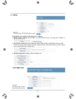
Page 32: ... 1 Camera Name Set the name of the IP Cam 2 MAC Address Display present network camera s MAC address 3 Get Address by PPPoE If your device is coonected to the WAN port of router that connects directly to external Internet network you need to select Get Address by PPPoE In addition you also need to set your PPPoE settings refer to the information provided by your ISP provider 4 Get Address by DHCP ...

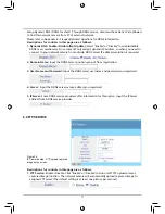
Page 33: ...s If you select Get Address by PPPoE Modem you need to inquire you ISP provider for relevant settings After changing the settings please click Apply button to save Otherwise please click Undo button to cancel the changes 5 3 WLAN SETUP Figure 20 IP Camera setup Wireless Network Setup Descriptions for controls in this page are as follows 1 Wireless opmode Ad Hoc Infrastructure Switches the wireless...

Page 34: ...as WPA AES encode key 4 KEY Input WEP or WPA encode key for encryption encoding described above Please input suitable length of digital key according to encryption type 5 IP setup Input IP address value and mode If PPPoE dial up connection mdoe is used and password is assigned by PPPoE router please select Get Address by PPPoE If your system IP is auto assigned by DHCP please select Get Address by...

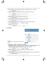
Page 35: ...nt IP address The settings can not be changed in this page If you want to change this setting please modify it in general network setup or wireless network setup After that please click Reload to reflect the latest address information 5 5 SYSTEM LOG Figure 22 IP Camera setup System Log information Display the system log of the network camera Please click Reload to retrieve the latest log Displayed...

Page 36: ...Defaults Yes No Restore your network camera s factory defaults and restart All the setting informations will be erased Please click Yes and click Apply button This is the same operation as hardware factory defaults restoring 7 Multiport Defaults Yes No Click Yes button to allow changing the network communication port For example you change the original network communication port from 80 to 8080 Th...

Page 37: ...up View Objects CamImage Class Step 6 Re login into IP Cam by inputting Username and password Step 7 Check the Current Version for successful update Note After Step 4 please do not operate IPCAM and power off it This will damage it and need to be sent back to factory for repair Strongly recommended Please use the connect method in section 2 2 to open browser and access to network monitoring screen...

Page 38: ...ntrary select Disable to disable this function 2 User Name password To automatically login PPPoE network input PPPoE username and password here and click Apply button to update settings Certain dial up ISP provider requires you to input PPPoE user s information 3 PPPoE Management Display present PPPoE status 5 8 DYNAMIC DNS Figure 25 IP Camera setup Dynamic Name Server setup screen ...

Page 39: ...equired 2 Domain Name Input the DDNS server position you got from registration 3 User Name and Password Input the DDNS server username and password you registered 4 Server Input the DDNS server service address you registered 5 IPServer Some DDNS service providers offer information for this option Input the IPServer address from DDNS service provider 5 9 FTP SERVICE Figure 26 IP Camera setup FTP up...

Page 40: ...ame FTP file name 5 10 E MAIL Figure 27 IP Camera setup E Mail upload captured image setup screen Descriptions for controls in this page are as follows 1 E mail Service Enable Disable Click Enable or Disable to turn on off the service of timely capturing and sending captured image to e mail address The netwrok camera will automatically capture image and upload it to assigned e mail address 2 Mail ...

Page 41: ...up screen Descriptions for controls in this page are as follows 1 Enable Time Zone Enable Disable Enable or disable time zone reference Enable or disable the time server on network and synchronize time Using time server can make your network camera has the most correct time for your saved image or film for storage and monitoring There are time servers available for public use on the network You ne...

Page 42: ...nput connectable time server IP address If you do not know available address please use following IP address or search in the Internet 5 Set time and Date Manually setup present date and time as below 6 Apply Undo After you change the settings please confirm the changes are correct and click Apply button to save them in the network camera You can also click Undo button to cancel the changes you ma...

Page 43: ...ifferent user levels Guest User Admin 3 Delete User Select the user number to be deleted and click Delete button to delete the user s data 4 Reload Reload all the users data 5 13 UPNP Figure 30 IP Camera setup Network Plug and Play switch 1 Enable UPnP Enable Disable Enable disable the UPnP function UPnP means network plug and play function To use this function please select and click Apply and th...

Page 44: ...ure D Figure B Figure C Figure D 3 Window shown as Figure E appears and please select Yes Y 4 Following installation window for component setup appears as Figure F 5 After completing setup the IP Cam in the same subnet appears and click it to connect as show in Figure G Figure E Figure F Figure G ...

Page 45: ... setup D Successfully using DDNS to view family use IPCAM A Using PC to apply the DDNS account You must first have an Ethernet based Cable ADSL modem using RJ 45 connector and make sure your broadband network is connected normally to Internet according to the method provided by ISP APPENDIX Step 1 Open PC and start broadband network and visit http www dyndns org website first Step 2 Switch to Acco...

Page 46: ...dns org and login using previous account and password Step 7 Open Account page and click Add Host next to Dynamic DNS as below Step 8 The screen automatically switches to Services page Please select Domain Name through scroll down menu gotdns com is used in this example Step 9 Fill in Host Name myipcam for this example and click Add Host to complete ...

Page 47: ...Connect IPCamFinder to HUB according to the figure below Step 2 Open and execute IPCamFinder Click Find IP Cam to search IPCams in the local network The names of IPCams found are listed in the list such as 00 15 0F 00 00 22 192 168 1 100 factory default Step 3 Open My Computer Control Panel Network and Dial up Connection Local Connection and click Properties P ...

Page 48: ... Step 6 In IPCamFinder click Find IP Cam again to search the IPCAMs in the local network again Click Show IP Cam to automatically start browser and open IPCAM login screen You can refer to the operation on P 56 to view IPCAM monitoring screen C Successfully using DDNS to view family use IPCAM Step 1 You can start browser and input set DDNS network address e g myipcam gotdns com to connect to IPCAM...

Page 49: ... the video images Can I use IP CAM outdoors The IP CAM is not waterproof You have to attach waterproof cover on it for using outdoors By the way we do not recommend you to do so What kind of network cable is necessary for IP CAM Standard RJ 45 Category 5 UTP twisted pair is necessary for IP CAM to connect 10 Base T and 100 Base T network communication Can I use IP CAM as general PC camera No IP CA...

Page 50: ... wrong with the focal distance of IP Cam How can I improve it Focus the IP CAM manually You can adjust the focal distance to a proper focal length If I forget IP password and IP address how can I connect and access IP CAM For the user who forget IP password and IP address please press and hold reset for eight seconds to return to the factory default settings When I complete the factory default set...

Page 51: ...t join to this IP Camera You can modify DMZ or NAT forwarding function of the router to assist the packets in Internet to be directed to this IP Camera correctly At the same time you can open DDNS function to make the network address connecting to this IP Camera easily and conveniently The power LED blinks for a long time What s wrong with it It might have trouble in power supply Please confirm th...

Page 52: ......

Reviews: