background image

Lambda 20, Lambda 40 UV/Vis Spectrometers 

40 


Designation Connector 

for  Remarks 

Accessory Port 

Linear transporter, 
multi-sipper 

I

2

C-bus interface 

Serial Port 

PC, (printer) 

First RS 232 C interface 

Parallel Port 

Printer Centronics 

interface 

J6, Autosampler 

AS90/91 autosampler 


J14, Cell Changer, Sipper 

Older accessories 

Active 

P15, 2

nd

 RS 232 

PC, printer 

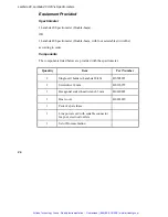
Second RS 232 C 
interface 

J10, J11, Temp 

Temperature sensor 

J10: 2-pin socket 
J11: 4-pin socket 

J30, Peltier 

Peltier cell changer 
and Peltier cell holder 

Active 

Te

m

p


P15 

Autosampler    J6 

Cell Changer 
Sipper 

2

nd

 RS232 

Peltier J30 

Sphere J8 

Parallel Port 

Serial Port 

Accessory Port 

J14 

J10 

J11 

J1 

Artisan Technology Group - Quality Instrumentation ... Guaranteed | (888) 88-SOURCE | www.artisantg.com

Summary of Contents for Lambda 20

Page 1: ...s underutilized and idle equipment along with credit for buybacks and trade ins Custom engineering so your equipment works exactly as you specify Critical and expedited services Leasing Rentals Demos In stock Ready to ship TAR certified secure asset solutions Expert team I Trust guarantee I 100 satisfaction All trademarks brand names and brands appearing herein are the property of their respective...

Page 2: ...Lambda 20 Lambda 40 Installation and Maintenance Guide Artisan Technology Group Quality Instrumentation Guaranteed 888 88 SOURCE www artisantg com ...

Page 3: ...or incidental consequential damages in connection with furnishing performance or use of this material Copyright Information This document contains proprietary information that is protected by copyright All rights are reserved No part of this publication may be reproduced in any form whatsoever or translated into any language without the prior written permission of PerkinElmer Inc Copyright 2000 Pe...

Page 4: ...20 Basic Installation 21 Basic Installation 23 Overview 23 Preparing the Working Area 23 Unpacking and Inspection 25 Equipment Provided 26 System Configuration 27 Connecting to the Electrical Supply 28 Single Cell Holder 29 Minimum Volume Applications 34 Setting up the Printer 35 Accessory Installation 37 Accessory Installation 39 General 39 Linear Transporter 43 Temperature Sensor 44 Multi sipper...

Page 5: ...the Internal Printer 66 Replacement Parts 69 Replacement Parts 71 System Description 73 System Description 75 Features 75 Optical System Lambda 20 75 Optical System Lambda 40 78 Technical Data 81 Technical Data 83 Lambda 20 83 Lambda 40 87 Translations of Warnings 91 Translations of Warnings 93 Index 103 Index 105 Artisan Technology Group Quality Instrumentation Guaranteed 888 88 SOURCE www artisa...

Page 6: ...Safety Information 1 Artisan Technology Group Quality Instrumentation Guaranteed 888 88 SOURCE www artisantg com ...

Page 7: ...Artisan Technology Group Quality Instrumentation Guaranteed 888 88 SOURCE www artisantg com ...

Page 8: ...ns Details about these circumstances are in a box like this one CAUTION We use the term CAUTION to inform you about situations that could result in serious damage to the instrument or other equipment Details about these circumstances are in a box like this one Translations of the warning messages used in this handbook are given in Translations of Warnings on page 93 Before using the instrument it ...

Page 9: ...I as defined in IEC 1010 1 Installation Category The instruments are able to withstand transient overvoltage according to Installation Category II as defined in IEC 1010 1 and IEC 664 Pollution Degree The equipment will operate safely in environments that contain non conductive foreign matter and condensation up to Pollution Degree 2 as defined in IEC 1010 1 and IEC 664 Electrical Safety To ensure...

Page 10: ...e instrument When the instrument is connected to line power terminals may be live and opening covers or removing parts except those to which access can be gained without the use of a tool is likely to expose live parts Capacitors inside the instrument may still be charged even if the instrument has been disconnected from all voltage sources When working with the instrument Connect the instrument t...

Page 11: ...is likely that the instrument is no longer electrically safe for use make the instrument inoperative and secure it against any unauthorized or unintentional operation The instrument is likely to be electrically unsafe when it Shows visible damage Fails to perform the intended measurement Has been subjected to prolonged storage under unfavorable conditions Has been subjected to severe transport str...

Page 12: ...e limits of a Class A digital device pursuant to Part 15 of the FCC Rules These limits are designed to provide reasonable protection against harmful interference when the equipment is operated in a commercial environment This equipment generates uses and can radiate radio frequency energy and if not installed and used in accordance with the instruction manual may cause harmful interference to radi...

Page 13: ...0 without condensation Altitude in the range 0 m to 2000 m Storage Conditions You can store the instrument safely under the following conditions Indoors Ambient temperature 15 ºC to 35 ºC Ambient relative humidity 20 to 80 without condensation Altitude in the range 0 m to 2000 m When you remove the instrument from storage before putting it into operation allow it to stand for at least a day under ...

Page 14: ...d disposal of waste must be in accordance with all national state and local health and safety regulations and laws OSHA Occupational Safety and Health Administration U S A ACGIH American Conference of Governmental Industrial Hygienists COSHH Control of Substances Hazardous to Health U K Toxic Fumes If you are working with volatile solvents or toxic substances you must provide an efficient laborato...

Page 15: ...ards presented by ultraviolet radiation When the deuterium UV lamp is illuminated do not open the spectrophotometer covers unless specifically instructed to do so in the manual Always wear UV absorbing eye protection when the deuterium lamp is exposed Never gaze into the deuterium lamp Symbols Used on the Instrument Figure 1 Lambda 20 40 Spectrometers Warning symbol shown on the spectrometer housi...

Page 16: ...5 Warning Labels on the Instrument Figure 2 Lambda 20 40 Spectrometers Warning labels shown on the inside of the lamp compartment Artisan Technology Group Quality Instrumentation Guaranteed 888 88 SOURCE www artisantg com ...

Page 17: ...GER HAUTE TENSION WARNING UV RADIATION HARMFUL TO THE EYES HOT COMPONENTS RISK OF BURNS ACHTUNG UV STRAHLUNG GEFÄHRDUNG DER AUGEN HEISSE BAUTEILE VERBRENNUNGSGEFAHR ATTENTION RADIATION UV DOMMAGEABLE POUR LES YEUX PARTIES CHAUDES RISQUE DE BRULURES Artisan Technology Group Quality Instrumentation Guaranteed 888 88 SOURCE www artisantg com ...

Page 18: ...Preface 2 Artisan Technology Group Quality Instrumentation Guaranteed 888 88 SOURCE www artisantg com ...

Page 19: ...Artisan Technology Group Quality Instrumentation Guaranteed 888 88 SOURCE www artisantg com ...

Page 20: ...ectrometers are usable in a wide range of applications as indicated by their performance specifications see Technical Data on page 83 Figure 3 Operating controls for Lambda 20 40 Spectrometers Lamp Compartment Power Switch Connector Panel Space for Optional Printer Sample Compartment Keyboard Keyboard and Display Cover Artisan Technology Group Quality Instrumentation Guaranteed 888 88 SOURCE www a...

Page 21: ...ation setup and maintenance procedures for the spectrometer It also includes a detailed description of the spectrometer and a list of consumables and replacement parts Operation Guide This handbook contains comprehensive information on operating the spectrometer and describes the parameters used Artisan Technology Group Quality Instrumentation Guaranteed 888 88 SOURCE www artisantg com ...

Page 22: ...Basic Installation 3 Artisan Technology Group Quality Instrumentation Guaranteed 888 88 SOURCE www artisantg com ...

Page 23: ...Artisan Technology Group Quality Instrumentation Guaranteed 888 88 SOURCE www artisantg com ...

Page 24: ... a cell changer or sipper refer to Accessory Installation on page 39 to install these accessories Preparing the Working Area For maximum stability and minimum maintenance observe the following requirements when siting the instrument A firm base free from vibration Enough space around and underneath the instrument for efficient air circulation A constant temperature between 15 ºC and 35 ºC Constant...

Page 25: ...cal Data on page 83 for the electrical ratings of the spectrometer The standard sample compartment baseplates have drain holes in them to run off spilled liquids to the benchtop underneath the instrument You can place a sheet of thick filter paper under the instrument if required Figure 4 Space Requirements Front view Right side view 56 cm 65 cm 26 cm Artisan Technology Group Quality Instrumentati...

Page 26: ...als fuse holders etc are not damaged 3 Open the sample compartment cover checking that it moves freely without binding The compartment must be free of dust or other foreign matter 4 Close the sample compartment cover 5 Open the lamp compartment as described in Halogen Lamp Replacement on page 56 6 Check for damages or loose cables 7 Close the lamp compartment NOTE We recommend that the initial ins...

Page 27: ...onents listed below are provided with the spectrometer Quantity Item Part Number 2 Single cell holders Lambda 20 40 B0505071 1 Screwdriver 4 mm B0126972 1 Hexagonal socket head wrench 3 mm B0140883 1 Dust cover B0142229 1 Pack of spare fuses 1 Line power cord with suitable connector for your electrical outlets 1 Set of Documentation Artisan Technology Group Quality Instrumentation Guaranteed 888 8...

Page 28: ...lacing instruments side by side always leave a small gap between them If you wish you can set up the printer on a separate trolley cart Make certain that air can circulate freely over and under the system as well as behind it CAUTION Do not place anything on or under any of the components that could hinder free air circulation Spectrometer External Printer option Artisan Technology Group Quality I...

Page 29: ...ng fuse is fitted 1 Make sure that the correct fuses are fitted in the holder at the rear of the spectrometer see Changing Fuses on page 65 Voltage Standard 100 V 120 V 6 3 A slow blow 210 V 240 V 3 15 A slow blow NOTE The module has two fuses 2 Make sure that the plug fitted to the line power cord provided with the spectrometer is suitable for your local electrical outlets If it is not remove it ...

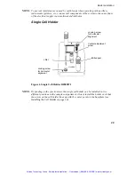
Page 30: ...NOTE Depending on the spectrometer the single cell holder can be installed in two different positions in the sample compartment Always install the holder such that the arrow on the cell holder lines up with the center point on the baseplate see Installing the Cell Holder on page 30 Locking screw for horizontal alignment Vertical adjustment screw Milled post Lifter Locking screw for horizontal alig...

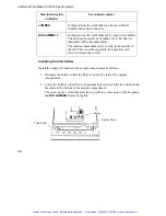
Page 31: ...pecially for operation with micro and semi micro cells Installing the Cell Holder Install the single cell holder in the sample compartment as follows 1 Orientate the holder so that the lifter is toward the rear of the sample compartment 2 Lower the holder so that the two alignment holes slip onto the two studs on the baseplate at the bottom of the sample compartment The arrow on the cell holder mu...

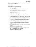
Page 32: ...erence cell holder Make certain that the cell is pushed down fully NOTE The alignment procedure is for a given cell in a given holder After alignment the cell should always be used in the same holder 4 Block the sample and reference beam window on the right hand side of the sample compartment with a card to prevent white light from saturating the detector 5 Return to standby display 6 Using the GO...

Page 33: ...cell window NOTE The center of the window for micro flowcells should be ideally approximately 15 mm above the base of the cell Figure 7 Correct Alignment of the Radiation Beam in the Cell Sample Area 10 If vertical alignment is required turn the vertical adjustment screw on the lifter either clockwise to raise the cell or counterclockwise to lower the cell 11 Recheck the horizontal alignment of th...

Page 34: ...ed posts loosened to obtain the highest possible transmittance reading on the display close sample compartment cover while measuring transmittance 6 Make vertical fine adjustment using the vertical adjustment screw again to obtain the highest possible reading close sample compartment cover while measuring transmittance 7 When you are satisfied with the alignment tighten the milled posts and the lo...

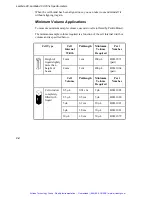
Page 35: ... is specified below Cell Type Cell Internal Width Pathlength Minimum Volume Required Part Number 2 mm 1 cm 200 µL B0631071 pair Height of liquid slightly more than height of beam 4 mm 1 cm 400 µL B0631064 pair Cell Volume Pathlength Minimum Volume Required Part Number 0 5 µL 0 01 cm 2 µL B0631082 2 5 µL 0 5 cm 5 µL B0631080 5 µL 0 1 cm 10 µL B0631083 5 µL 1 0 cm 10 µL B0631081 Cell window complete...

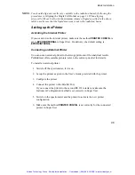
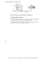
Page 36: ... You can use an external printer for hard copy printouts of the analytical results PerkinElmer offers suitable printers refer to the current price list for details To install an external printer 1 Switch off the spectrometer if it is on 2 Set up the printer as given in the User s Guide provided with the printer 3 Configure the printer 4 Connect the printer to the Parallel Port If you connect the p...

Page 37: ...y configured for your printer type as described in Super User printer configuration in the Operation handbook With Epson printers make sure the printer parameter is configured correctly for the type of paper you are using Z fold paper or single sheet Printer Printer Cable Spectrometer Artisan Technology Group Quality Instrumentation Guaranteed 888 88 SOURCE www artisantg com ...
Page 38: ...Accessory Installation 4 Artisan Technology Group Quality Instrumentation Guaranteed 888 88 SOURCE www artisantg com ...
Page 39: ...Artisan Technology Group Quality Instrumentation Guaranteed 888 88 SOURCE www artisantg com ...

Page 40: ...ove the sample compartment cover The required procedures are described below In the directions provided with some sample handling accessories reference is made to earlier models in the Lambda Series of spectrometers These directions are generally applicable to the current series of instruments since the sample compartment is standardized Accessory Connector Panel LP5 5 To facilitate manufacturing ...

Page 41: ...sampler J14 Cell Changer Sipper Older accessories Active P15 2 nd RS 232 PC printer Second RS 232 C interface J10 J11 Temp Temperature sensor J10 2 pin socket J11 4 pin socket J30 Peltier Peltier cell changer and Peltier cell holder Active Temp P15 Autosampler J6 Cell Changer Sipper 2 nd RS232 Peltier J30 Sphere J8 Parallel Port Serial Port Accessory Port J14 J10 J11 J1 Artisan Technology Group Qu...

Page 42: ...hanger Sipper 2 nd RS232 Peltier J30 Sphere J8 Parallel Port Serial Port Accessory Port J14 J10 J1 J11 Temp Autosampler Peltier Cell Holder Peltier Cell Changer Temperature Sensor External Printer Older Accessories Linear Transporter Multi sipper PC P15 Artisan Technology Group Quality Instrumentation Guaranteed 888 88 SOURCE www artisantg com ...

Page 43: ...e Compartment Front Cover Some of the accessories used with the spectrometer require removal of the sample compartment front cover Do this carefully as follows 1 Open the sample compartment cover 2 Carefully slide the cover straight up off both hinges to remove You install the sample compartment cover or other accessory cover by performing this procedure in reverse Sample Compartment Window To rem...

Page 44: ...upply before you alter or make any new electrical connections Installation Overview Connector on Spectrometer Accessory Port Installation See linear transporter handbook Cables Lead through bottom of spectrometer housing Tubes Lead through the tube ports Sample Compartment Cover Unchanged Alignment See linear transporter handbook Artisan Technology Group Quality Instrumentation Guaranteed 888 88 S...

Page 45: ...l connections Installation Overview NOTE When connecting the temperature sensor align the red mark on the plug with the red mark on the socket Pull the collar on the plug back to connect disconnect the plug Release the collar to secure the plug Connector on Spectrometer Temp J10 Installation See temperature sensor description Cables Lead through the tube ports Sample Compartment Cover Unchanged Ar...

Page 46: ...er supply before you alter or make any new electrical connections Installation Overview Connector on Spectrometer Accessory Port Installation See sipper manual Cables See sipper manual Tubes See sipper manual Sample Compartment Cover Unchanged Figure 9 Multi sipper electrical connection Multi sipper Spectrometer B0167808 Artisan Technology Group Quality Instrumentation Guaranteed 888 88 SOURCE www...

Page 47: ...em from the line power supply before you alter or make any new electrical connections Installation Overview Connector on Spectrometer Autosampler Installation See autosampler manual Cables See autosampler manual Tubes See autosampler manual Figure 10 Autosampler electrical connection Autosampler Spectrometer B0509311 Artisan Technology Group Quality Instrumentation Guaranteed 888 88 SOURCE www art...

Page 48: ...S 232 port is configured for use with a PC default see Super User method RS232 PORT CONFIG To operate the spectrometer via the PC you additionally require a PerkinElmer UV software package for example UV WinLab PECSS Ask your PerkinElmer service representative for more details Artisan Technology Group Quality Instrumentation Guaranteed 888 88 SOURCE www artisantg com ...
Page 49: ...Lambda 20 Lambda 40 UV Vis Spectrometers 48 Artisan Technology Group Quality Instrumentation Guaranteed 888 88 SOURCE www artisantg com ...
Page 50: ...Maintenance 5 Artisan Technology Group Quality Instrumentation Guaranteed 888 88 SOURCE www artisantg com ...
Page 51: ...Artisan Technology Group Quality Instrumentation Guaranteed 888 88 SOURCE www artisantg com ...
Page 52: ...strument except as described in the accompanying User Documentation Only a PerkinElmer service representative or similarly trained and authorized person should be permitted to service the instrument Daily Care The instrument is constructed with high quality components and requires little maintenance other than to keep it clean and free of dust To protect the optical system from dust and fumes you ...

Page 53: ...aned at the end of the working day Generally such systems should be filled with deionized water when left overnight CAUTION Risk of damage to Optics or Electronics Take care not to spill liquids onto the spectrometer Expensive damage can result to the optics or electronics if liquids are spilled and run inside the instrument or onto the keyboard Cleaning the Sample Compartment You must clean the s...

Page 54: ...ectral range of the spectrometer The window seals the sample compartment and thus protects the instrument s optics from dust and fuming or aggressive samples Generally the window should be installed at all times The window is an optical component and requires the same care and handling as cells You can remove the window to clean it The frame is magnetic and can be removed by hand Windows are most ...

Page 55: ... hard surfaces Avoid abrasive corrosive or stain producing cleaning agents and make certain that the exposed surfaces of cells are optically clean Always wipe the optical surfaces of cells dry and free of fingermarks using a soft cloth or cleaning tissue just before placing them in the cell holder When measuring cold solutions always bear in mind that condensation can form on the optical surfaces ...

Page 56: ...to fill the cell completely insert the stopper only lightly so that the liquid in the cell has a chance to expand Do not insert a stopper forcefully into a completely filled cell since this is likely to cause the cell to burst When working at higher temperatures use a drilled stopper 0 4 mm hole to allow for expansion in the cell Replacing a Lamp Figure 11 Lamp compartment Lamp compartment Artisan...

Page 57: ...mes blackened after prolonged use you should replace the lamp Replacement lamp assemblies are provided complete with prealigned mounts Part Number B0114620 Halogen lamp assembly Lamp energy attenuator White ceramic connector Deuterium lamp connector Deuterium lamp assembly Artisan Technology Group Quality Instrumentation Guaranteed 888 88 SOURCE www artisantg com ...

Page 58: ...amps emit intense radiation which can damage your eyes Do not open the lamp compartment when the lamps are on Do not gaze into a lighted lamp 1 Switch off the spectrometer and unplug the line power cord 2 Remove the lamp compartment cover by pressing down the catch and pushing the cover to the left 3 Remove the lamp baffle by slackening the thumbscrew for the deuterium lamp and lifting the lamp ba...

Page 59: ...y pull the white ceramic connector from the rear of the halogen lamp Lamp baffle Thumbscrew deuterium lamp Thumbscrew Halogen lamp assembly White ceramic connector Artisan Technology Group Quality Instrumentation Guaranteed 888 88 SOURCE www artisantg com ...

Page 60: ...nector firmly onto the pins on the base of the lamp 9 Wipe the bulb with a soft cloth moistened with alcohol to remove dirt since this would otherwise be burned in when the lamp is hot 10 Replace the lamp baffle using the reverse of the procedure described in step 3 11 Replace the lamp compartment cover This completes the halogen lamp replacement procedure Deuterium Lamp Replacement If the lamp bu...

Page 61: ...ing with the replacement Risk of Burns If the old lamp was lighted allow it to cool before proceeding with the replacement UV Radiation The lamps emit intense radiation which can damage your eyes Do not open the lamp compartment when the lamps are on Do not gaze into a lighted lamp 1 Switch off the spectrometer and unplug the line power cord 2 Remove the lamp compartment cover by pressing down the...

Page 62: ...r vertically upward 5 Remove the lamp assembly from the bracket by slackening the thumbscrew and pulling the lamp mount vertically upward Save the thumbscrew for use with the new lamp assembly Lamp baffle Thumbscrew deuterium lamp Deuterium lamp connector Deuterium lamp assembly Artisan Technology Group Quality Instrumentation Guaranteed 888 88 SOURCE www artisantg com ...

Page 63: ...pt to insert the connector by force 9 Wipe the lamp window with a soft cloth moistened with alcohol to remove dirt since this would otherwise be burned in when the lamp is hot 10 Replace the lamp baffle using the reverse of the procedure described in step 3 11 Replace the lamp compartment cover This completes the deuterium lamp replacement procedure Lamp Energy Attenuator An attenuator is located ...

Page 64: ...iation which can damage your eyes Do not open the lamp compartment when the lamps are on Do not gaze into a lighted lamp Operate the attenuator as follows 1 Open the lamp compartment 2 Remove the lamp baffle by slackening the thumbscrew for the deuterium lamp and lifting the lamp baffle vertically upward 3 Loosen the thumbscrew holding the attenuator in place Lamp baffle Thumbscrew deuterium lamp ...

Page 65: ...eplace the lamp baffle using the reverse of the procedure described in step 2 8 Close the lamp compartment Lamp Alignment Procedure Due to the prealigned mounts the alignment of lamps after installation is generally so good that further alignment is not required Lamp energy attenuator Deuterium lamp assembly Artisan Technology Group Quality Instrumentation Guaranteed 888 88 SOURCE www artisantg co...

Page 66: ...u alter or make any new electrical connections The fuses are located in a fuse holder at the rear of the instrument Figure 15 Rear view Fuse Holder 1 Switch off the instrument and remove the line power cord from the electrical supply 2 Squeeze the two lugs at each side of the fuse holder and gently pull out Fuse Holder Fuse Holder Artisan Technology Group Quality Instrumentation Guaranteed 888 88 ...

Page 67: ... but the instrument still does not work correctly or the fuses blow repeatedly contact your PerkinElmer office or representative Maintaining the Internal Printer The internal printer needs no special maintenance You only need to Change the printer paper Change the printer ribbon when necessary Changing the Printer Paper 1 Lift off and remove the old paper roll 2 Replace with a new paper roll 3 Cut...

Page 68: ...emove the paper roll 2 Push in the catch on the printer cover 3 Carefully lift out the printer 4 Gently pull the ribbon cassette forwards to remove 5 Replace with a new one 6 Replace the printer and printer cover using the reverse of the above procedure Artisan Technology Group Quality Instrumentation Guaranteed 888 88 SOURCE www artisantg com ...

Page 69: ...Lambda 20 Lambda 40 UV Vis Spectrometers 68 Artisan Technology Group Quality Instrumentation Guaranteed 888 88 SOURCE www artisantg com ...

Page 70: ...Replacement Parts 6 Artisan Technology Group Quality Instrumentation Guaranteed 888 88 SOURCE www artisantg com ...

Page 71: ...Artisan Technology Group Quality Instrumentation Guaranteed 888 88 SOURCE www artisantg com ...

Page 72: ...e Supplies Catalog for Ultraviolet Visible and Fluorescence Spectroscopy and Polarimetry To place an order request a free catalog or ask for information If you are located within the U S call toll free 1 800 762 402 8 a m to 8 p m EST Your order will be shipped promptly usually within 24 hours If you are located outside of the U S call your local PerkinElmer sales office Artisan Technology Group Q...

Page 73: ...um Lamp prealigned B2000501 1 Halogen Lamp prealigned B0114620 1 Thumbscrew for lamp mount B0119371 1 Sample Compartment Window B0098757 Cells and Cell Holder Cells see actual price list 1 Single Cell Holder B0505071 Miscellaneous 5 Paper Roll for internal printer B0508751 1 Ribbon for internal printer B0508752 Artisan Technology Group Quality Instrumentation Guaranteed 888 88 SOURCE www artisantg...

Page 74: ...System Description 7 Artisan Technology Group Quality Instrumentation Guaranteed 888 88 SOURCE www artisantg com ...

Page 75: ...Artisan Technology Group Quality Instrumentation Guaranteed 888 88 SOURCE www artisantg com ...

Page 76: ...rating is used in the monochromator The optical system is depicted schematically in Figure 17 The monochromator is a holographic concave grating with 1053 lines mm in the center Two radiation sources a deuterium lamp and a halogen lamp cover the working wavelength range of the spectrometer Keyboard and Display Cover Lamp compartment Power switch Connector panel Sample compartment Artisan Technolog...

Page 77: ...el assembly A stepping motor drives the filter wheel to be in sychronization with the monochromator Depending on the wavelength being produced the appropriate optical filter is located in the beam path to prefilter the radiation before it enters the monochromator Filter change is automatic during monochromator slewing From the optical filter the radiation passes through the entrance slit Slit 1 of...

Page 78: ...50 of the radiation to pass onto plane mirror M4 and reflects 50 of the radiation onto plane mirror M5 Mirror M4 focuses the radiation beam in the sample cell Halogen lamp Deuterium lamp Filter wheel M2 M1 Slit 1 Slit 2 M5 Reference Sample M3 Detector Lens Lens Detector M4 Grating Monochromator Beam Splitter M Mirror M1 M4 and M5 Plane Mirror M2 Toroidal Mirror M3 Spherical Mirror Artisan Technolo...

Page 79: ...ror M1 reflects the radiation from the halogen lamp onto source mirror M2 At the same time M1 blocks the radiation from the deuterium lamp For operation in the ultraviolet UV range mirror M1 is raised to permit radiation from the deuterium lamp to strike source mirror M2 Source change is automatic during monochromator slewing Radiation from the source lamp is reflected from source mirror M2 throug...

Page 80: ...ss of 0 5 nm 1 nm 2 nm and 4 nm From mirror M3 the radiation is reflected onto a beam splitter which allows 50 of the radiation to pass onto plane mirror M4 and reflects 50 of the radiation onto plane mirror M5 Mirror M4 focuses the radiation beam in the sample cell Halogen lamp Deuterium lamp Filter wheel M2 M1 Selectable Slit 1 Selectable Slit 2 M5 Reference Sample M3 Detector Lens Lens Detector...

Page 81: ...ough a convex lens onto the photodiode detector Mirror M5 focuses the radiation beam in the reference cell The beam then passes through a convex lens onto the photodiode detector Artisan Technology Group Quality Instrumentation Guaranteed 888 88 SOURCE www artisantg com ...

Page 82: ...Technical Data 8 Artisan Technology Group Quality Instrumentation Guaranteed 888 88 SOURCE www artisantg com ...

Page 83: ...Artisan Technology Group Quality Instrumentation Guaranteed 888 88 SOURCE www artisantg com ...

Page 84: ... 60 Hz 250 VA Ambient operating temperature 15 ºC to 35 ºC Humidity range 20 to 80 relative humidity without condensation Technical Standard In compliance with the requirements for technical instruments stipulated by IEC 1010 1 9 90 Radio interference suppression In compliance with the legal requirements of the EMC directive 89 336 EEC EN 50 081 1 EN 50 082 1 Artisan Technology Group Quality Instr...

Page 85: ... the center Radiation sources Prealigned deuterium and halogen lamps Detector Photodiodes One for the sample beam and one for the reference beam Abscissa Wavelength range 190 n to 1100 nm 0 nm for alignment purposes Wavelength accuracy 0 3 nm Wavelength reproducibility 0 1 nm Spectral bandwidth 1 nm or 2 nm fixed slit Lamp change Automatically at 326 nm selectable over the whole wavelength range s...

Page 86: ...smission 0 02 at 220 nm 340 nm and 370 nm Absorbance 2 measured at 200 nm with potassium chloride solution against distilled water Baseline linearity 1 nm slit Absorbance 0 001 2 nm slit Absorbance 0 0005 corrected 200 nm to 100 nm scan speed 240 nm min smooth 2 Baseline noise 1 nm slit Absorbance 0 00008 RMS Absorbance 0 0003 peak to peak 3 min at absorbance 0 wavelength 500 nm and response 2 s β...

Page 87: ...ng a printer or PC optional second RS 232 C interface Display Information parameters and entries are shown on a two line vacuum fluorescence display with 20 alphanumeric characters per line Methods Types Timedrive Scan Wavelength Program Concentration Analysis with factor and with Calibration Artisan Technology Group Quality Instrumentation Guaranteed 888 88 SOURCE www artisantg com ...

Page 88: ...V AC 50 60 Hz 250 VA Ambient operating temperature 15 ºC to 35 ºC Humidity range 20 to 80 relative humidity without condensation Technical Standard In compliance with the requirements for technical instruments stipulated by IEC 1010 1 9 90 Radio interference suppression In compliance with the legal requirements of the EMC directive 89 336 EEC EN 50 081 1 EN 50 082 1 Artisan Technology Group Qualit...

Page 89: ... Optical pathlength in sample compartment 121 mm Grating Monochromator Holographic concave grating with 1053 lines mm in the center Radiation sources Prealigned deuterium and halogen lamps Detector Photodiodes One for the sample beam and one for the reference beam Abscissa Wavelength range 190 nm to 1100 nm 0 nm for alignment purposes Wavelength accuracy 0 3 nm Wavelength reproducibility 0 1 nm Sp...

Page 90: ...at 440 nm 546 1 nm and 635 nm with NIST 930 filters Absorbance 0 015 measured at Absorbance 1 at 257 nm and 350 nm with potassium dichromate solution Stray radiation Transmission 0 02 at 220 nm 340 nm and 370 nm Absorbance 2 measured at 200 nm with potassium chloride solution against distilled water Baseline linearity 2 nm slit Absorbance 0 0005 corrected 200 nm to 100 nm scan speed 240 nm min smo...

Page 91: ... Data Output Digital port One RS 232 C interface serial for connecting a printer or PC optional second RS 232 C interface Display Information parameters and entries are shown on a two line vacuum fluorescence display with 20 alphanumeric characters per line Methods Types Timedrive Scan Wavelength Program Concentration Analysis with factor and with Calibration Artisan Technology Group Quality Instr...

Page 92: ...Translations of Warnings 9 Artisan Technology Group Quality Instrumentation Guaranteed 888 88 SOURCE www artisantg com ...

Page 93: ...Artisan Technology Group Quality Instrumentation Guaranteed 888 88 SOURCE www artisantg com ...
Page 94: ...tions of Warnings 93 Translations of Warnings This annex contains translations of the warnings used in this handbook Artisan Technology Group Quality Instrumentation Guaranteed 888 88 SOURCE www artisantg com ...

Page 95: ...Lambda 20 Lambda 40 UV Vis Spectrometers 94 Artisan Technology Group Quality Instrumentation Guaranteed 888 88 SOURCE www artisantg com ...

Page 96: ...Translations of Warnings 95 Artisan Technology Group Quality Instrumentation Guaranteed 888 88 SOURCE www artisantg com ...

Page 97: ...Lambda 20 Lambda 40 UV Vis Spectrometers 96 Artisan Technology Group Quality Instrumentation Guaranteed 888 88 SOURCE www artisantg com ...

Page 98: ...Translations of Warnings 97 Artisan Technology Group Quality Instrumentation Guaranteed 888 88 SOURCE www artisantg com ...

Page 99: ...Lambda 20 Lambda 40 UV Vis Spectrometers 98 Artisan Technology Group Quality Instrumentation Guaranteed 888 88 SOURCE www artisantg com ...

Page 100: ...Translations of Warnings 99 Artisan Technology Group Quality Instrumentation Guaranteed 888 88 SOURCE www artisantg com ...

Page 101: ...Lambda 20 Lambda 40 UV Vis Spectrometers 100 Artisan Technology Group Quality Instrumentation Guaranteed 888 88 SOURCE www artisantg com ...

Page 102: ...Translations of Warnings 101 Artisan Technology Group Quality Instrumentation Guaranteed 888 88 SOURCE www artisantg com ...

Page 103: ...Lambda 20 Lambda 40 UV Vis Spectrometers 102 Artisan Technology Group Quality Instrumentation Guaranteed 888 88 SOURCE www artisantg com ...

Page 104: ...Index 10 Artisan Technology Group Quality Instrumentation Guaranteed 888 88 SOURCE www artisantg com ...

Page 105: ...Artisan Technology Group Quality Instrumentation Guaranteed 888 88 SOURCE www artisantg com ...

Page 106: ... 29 System Configuration 27 Unpacking and Inspection 25 C Cleaning the Sample Compartment 52 Connecting up the Printer Configuring an External Printer 36 D Deuterium Lamp Replacement 59 F Fuses Changing 65 H Halogen Lamp Replacement 56 I Internal Printer Changing the Printer Paper 66 Changing the Printer Ribbon 67 Maintaining 66 L Lambda 20 Optical system 75 Technical data 83 Lambda 40 Optical sys...

Page 107: ...ection 8 Electrical Safety 8 Environment 12 Graphic Symbols Used on the Instrument 14 IEC 1010 Compliance 8 UL Compliance 8 UV Radiation 14 Setting up the Printer 35 Connecting an External Printer 35 Single Cell Holder 29 Aligning 31 Fine Alignment 33 Installing 30 Minimum Volume Applications 34 System Configuration 27 System Description 75 Features 75 Optical System Lambda 20 75 Optical System La...

Page 108: ...quipment Have surplus equipment taking up shelf space We ll give it a new home Learn more Visit us at artisantg com for more info on price quotes drivers technical specifications manuals and documentation Artisan Scientific Corporation dba Artisan Technology Group is not an affiliate representative or authorized distributor for any manufacturer listed herein We re here to make your life easier How...

Reviews: