Installation
108
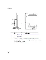
3. Firmly slide the torch coupler, clockwise, into the torch mount so the two
locking lugs and guide pin in the torch coupler engage the channels in the torch
mount. Rotate the torch coupler completely clockwise until it cannot be rotated
any further. See the following figure.
4. For proper ignition, turn the torch coupler fully clockwise and continue an
additional 2 mm from where you want to go. For example, to set at -3 loosen the
locking thumbscrew nut (but do not unthread) and move the torch clockwise to
the 1 position. Then go back to the desired position of -3 and tighten the locking
thumbscrew nut.
If in the future when you remove the torch coupler and then gently rotate to the
locked position you will not have to reset it. The torch coupler will return to the
locked position that you set earlier.
Note
For recommended torch positions, see
Setting Instrument Parameters
on
page 123.
Summary of Contents for OPTIMA 8000
Page 1: ...OPTIMA 8000 Customer Hardware and Service Guide ICP OPTICAL EMISSION Return to Document Menu...
Page 2: ......
Page 3: ...Optima 8000 Customer Hardware and Service Manual...
Page 12: ...Contents 10...
Page 18: ...16 Indicates the ON position of the main power switch Indicates alternating current...
Page 24: ...22 Figure C Location of warning labels in the sample compartment 1 2...
Page 28: ...26...
Page 29: ...Safety Practices 1...
Page 49: ...Preparing Your Laboratory 2...
Page 61: ...Preparing Your Laboratory 60...
Page 62: ...System Description 3...
Page 89: ...Installation 4...
Page 136: ...Maintenance 5...
Page 241: ...Troubleshooting 6...
Page 264: ...Error Messages 7...
Page 284: ......


